SYSTEM INTEGRATION MODULE MC68332
4-2 USER’S MANUAL
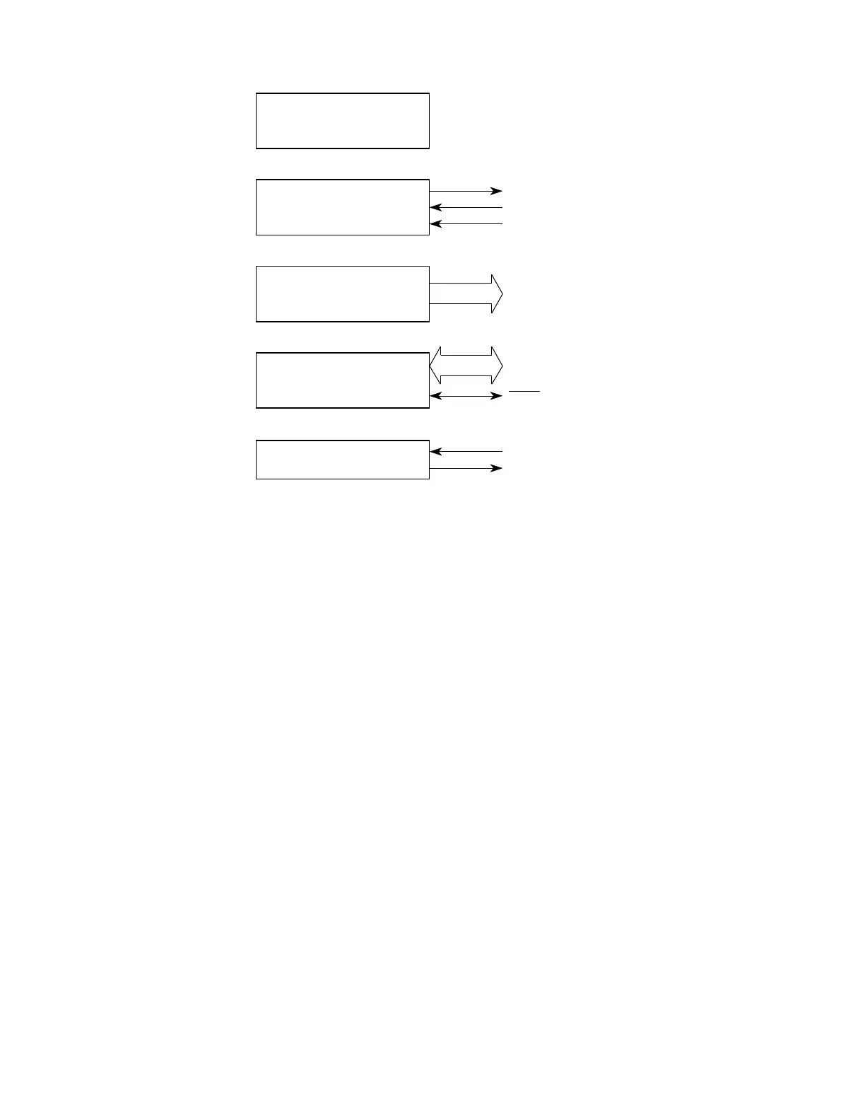
Figure 4-1 System Integration Module Block Diagram
4.2 System Configuration and Protection
The system configuration and protection functional block controls module configura-
tion, preserves reset status, monitors internal activity, and provides periodic interrupt
generation. Figure 4-2 is a block diagram of the submodule.
S(C)IM BLOCK
SYSTEM CONFIGURATION
AND PROTECTION
CLOCK SYNTHESIZER
CHIP SELECTS
EXTERNAL BUS INTERFACE
FACTORY TEST
CLKOUT
EXTAL
MODCLK
CHIP SELECTS
EXTERNAL BUS
RESET
TSC
FREEZE/QUOT
Fr
ees
cale S
em
iconduct
or
, I
Freescale Semiconductor, Inc.
For More Information On This Product,
Go to: www.freescale.com
nc...