QUEUED SERIAL MODULE MC68332
6-8 USER’S MANUAL
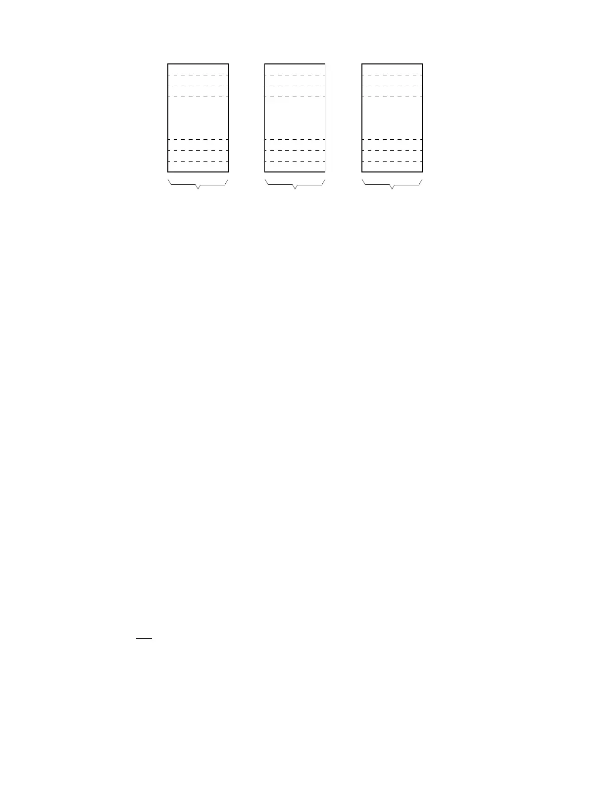
Figure 6-3 QSPI RAM
6.3.2.2 Transmit RAM
Data that is to be transmitted by the QSPI is stored in this segment. The CPU normally
writes one word of data into this segment for each queue command to be executed.
Information to be transmitted must be written to transmit RAM in a right-justified for-
mat. The QSPI cannot modify information in the transmit RAM. The QSPI copies the
information to its data serializer for transmission. Information remains in transmit RAM
until overwritten.
6.3.2.3 Command RAM
Command RAM is used by the QSPI in master mode. The CPU writes one byte of con-
trol information to this segment for each QSPI command to be executed. The QSPI
cannot modify information in command RAM.
Command RAM consists of 16 bytes. Each byte is divided into two fields. The periph-
eral chip-select field enables peripherals for transfer. The command control field pro-
vides transfer options.
A maximum of 16 commands can be in the queue. Queue execution by the QSPI pro-
ceeds from the address in NEWQP through the address in ENDQP (both of these
fields are in SPCR2).
6.3.3 QSPI Pins
The QSPI uses seven pins. These pins can be configured for general-purpose I/O
when not needed for QSPI application. When used for QSPI functions, the MOSI, MI-
SO, and SS
pins should have pull-up resistors.
Table 6-2 shows QSPI input and output pins and their functions.
QSPI RAM MAP
RECEIVE
RAM
TRANSMIT
RAM
D00
D1E
D20
D3E
WORD
D40
D4F
COMMAND
RAM
BYTEWORD
RR0
RR1
RR2
RRD
RRE
RRF
TR0
TR1
TR2
TRD
TRE
TRF
CR0
CR1
CR2
CRD
CRE
CRF
Fr
ees
cale S
em
iconduct
or
, I
Freescale Semiconductor, Inc.
For More Information On This Product,
Go to: www.freescale.com
nc...