ELECTRICAL CHARACTERISTICS MC68332
A-12 USER’S MANUAL
30A CLKOUT Low to Data In High Impedance
7
t
CLDH
—72ns
31 DSACK[1:0]
Asserted to Data In Valid
9
t
DADI
—46ns
33 Clock Low to BG
Asserted/Negated t
CLBAN
—23ns
35 BR
Asserted to BG Asserted (RMC Not Asserted)
10
t
BRAGA
1—t
cyc
37 BGACK Asserted to BG Negated t
GAGN
12t
cyc
39 BG Width Negated t
GH
2—t
cyc
39A BG Width Asserted t
GA
1—t
cyc
46 R/W Width Asserted (Write or Read) t
RWA
115 — ns
46A R/W
Width Asserted (Fast Write or Read Cycle) t
RWAS
70 — ns
47A Asynchronous Input Setup Time
BR
, BGACK, DSACK[1:0], BERR, AVEC, HALT
t
AIST
5—ns
47B Asynchronous Input Hold Time t
AIHT
12 — ns
48 DSACK[1:0]
Asserted to BERR, HALT Asserted
11
t
DABA
—30ns
53 Data Out Hold from Clock High t
DOCH
0—ns
54 Clock High to Data Out High Impedance t
CHDH
—23ns
55 R/W
Asserted to Data Bus Impedance Change t
RADC
32 — ns
56 RESET
Pulse Width (Reset Instruction) t
HRPW
512 — t
cyc
57 BERR Negated to HALT Negated (Rerun) t
BNHN
0—ns
70 Clock Low to Data Bus Driven (Show) t
SCLDD
023ns
71 Data Setup Time to Clock Low (Show) t
SCLDS
10 — ns
72 Data Hold from Clock Low (Show) t
SCLDH
10 — ns
73 BKPT
Input Setup Time t
BKST
10 — ns
74 BKPT
Input Hold Time t
BKHT
10 — ns
75 Mode Select Setup Time t
MSS
20 — t
cyc
76 Mode Select Hold Time t
MSH
0—ns
77 RESET
Assertion Time
12
t
RSTA
4—t
cyc
78 RESET Rise Time
13,14
t
RSTR
—10t
cyc
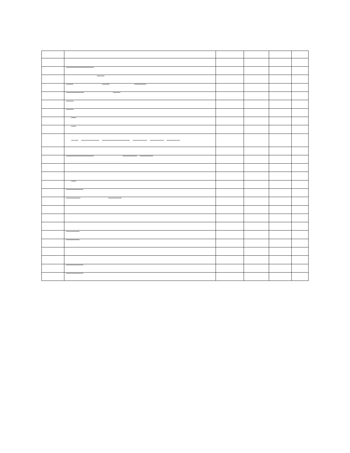
Table A-6a. 20.97 MHz AC Timing (Continued)
(V
DD
and V
DDSYN
= 5.0 Vdc ± 5%, V
SS
= 0 Vdc, T
A
= T
L
to T
H
)
Num Characteristic Symbol Min Max Unit
Fr
ees
cale S
em
iconduct
or
, I
Freescale Semiconductor, Inc.
For More Information On This Product,
Go to: www.freescale.com
nc...