148
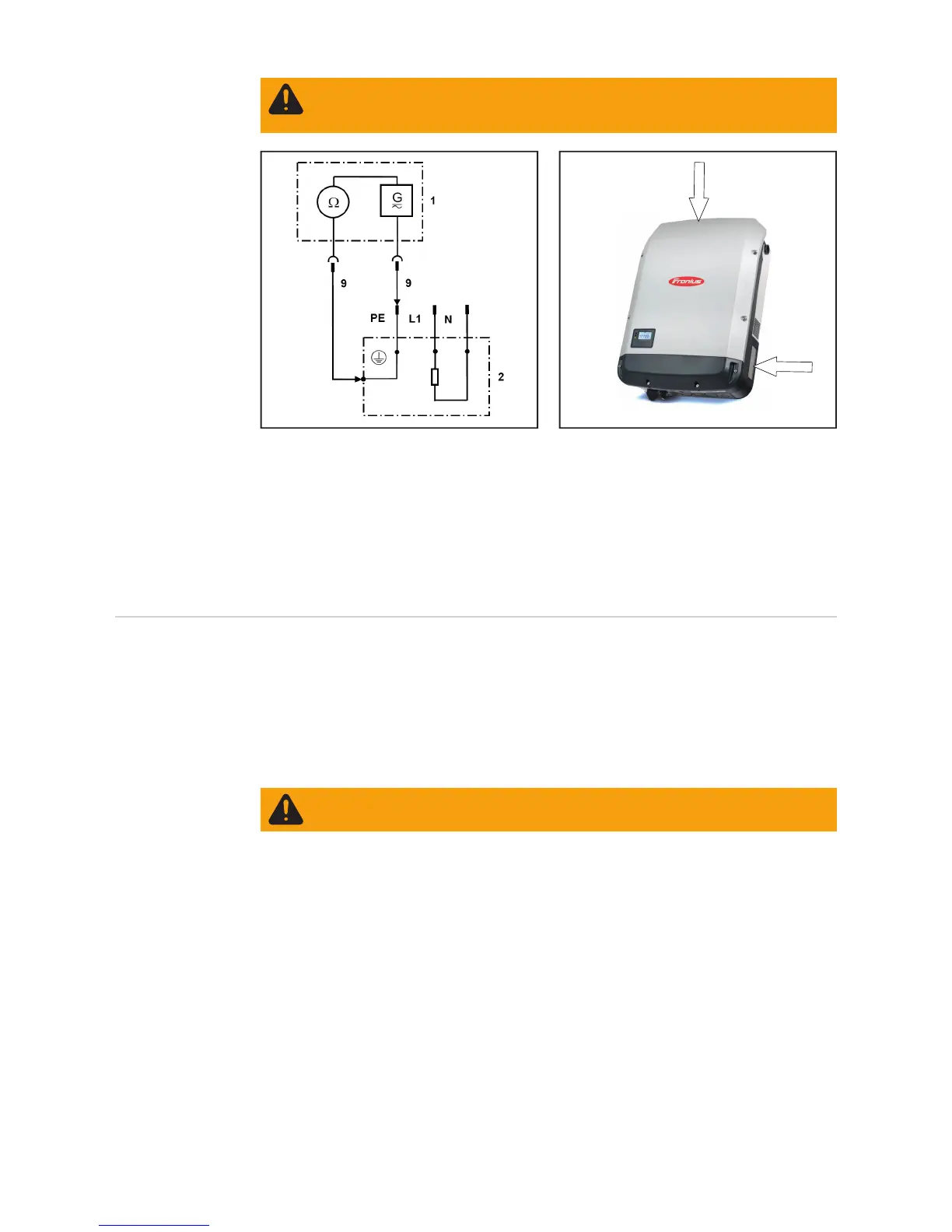
1 Measuring device
2 Inverter
9 Measuring line
Example: Measuring the ground conductor resistance
(A) - release the on power stage set cover
- if necessary, the wall bracket must be lightly
scratched to penetrate the eloxal or powder coating
- The resistance must not exceed 0.3 *)
*) These requirements comply with DIN VDE 0701-0702 and ÖVE/ÖNORM E8701-1. Also
refer to the applicable requirements and standards in your country.
Ground conduc-
tor current
Preparations
- Only perform the measurement if a ground conductor resistance test has been carried
out successfully
- Direct method: The device must be isolated from earth. No other connections to the
ground potential are permitted (e.g. data lines, fitting, etc.)
- Remove conductive objects from the housing
- Fit any missing housing parts
Once the inverter has been connected, switch it back on. The inverter must be feeding en-
ergy during the measurement to avoid unreliable results.
Only the leakage currents that occur at grid frequency may be included (50 - 60 Hz function
of ammeter). High-frequency leakage currents distort the measurement results *).
*) These requirements comply with DIN VDE 0701-0702 and ÖVE/ÖNORM E8701-1. Also
refer to the applicable requirements and standards in your country.
There are two methods that may be used to measure the ground conductor current:
- Direct method: Device must be completely isolated and must not exhibit any links to
another earth potential
- Differential method
The measurement can be taken on the inverter (loop outside the device) or in the distribu-
tor. If taking the measurement in the distributor, ensure that there are no live conductors in
the immediate vicinity and that no other consumers are connected to the same circuit.
WARNING! Set the inverter DC disconnector to the 0 position and place the in-
verter in the wall bracket. Placing the inverter in the wall bracket causes a voltage
to be applied to the inverter.
WARNING! An electric shock can be fatal. The inverter is live during the meas-
urement.
 Loading...