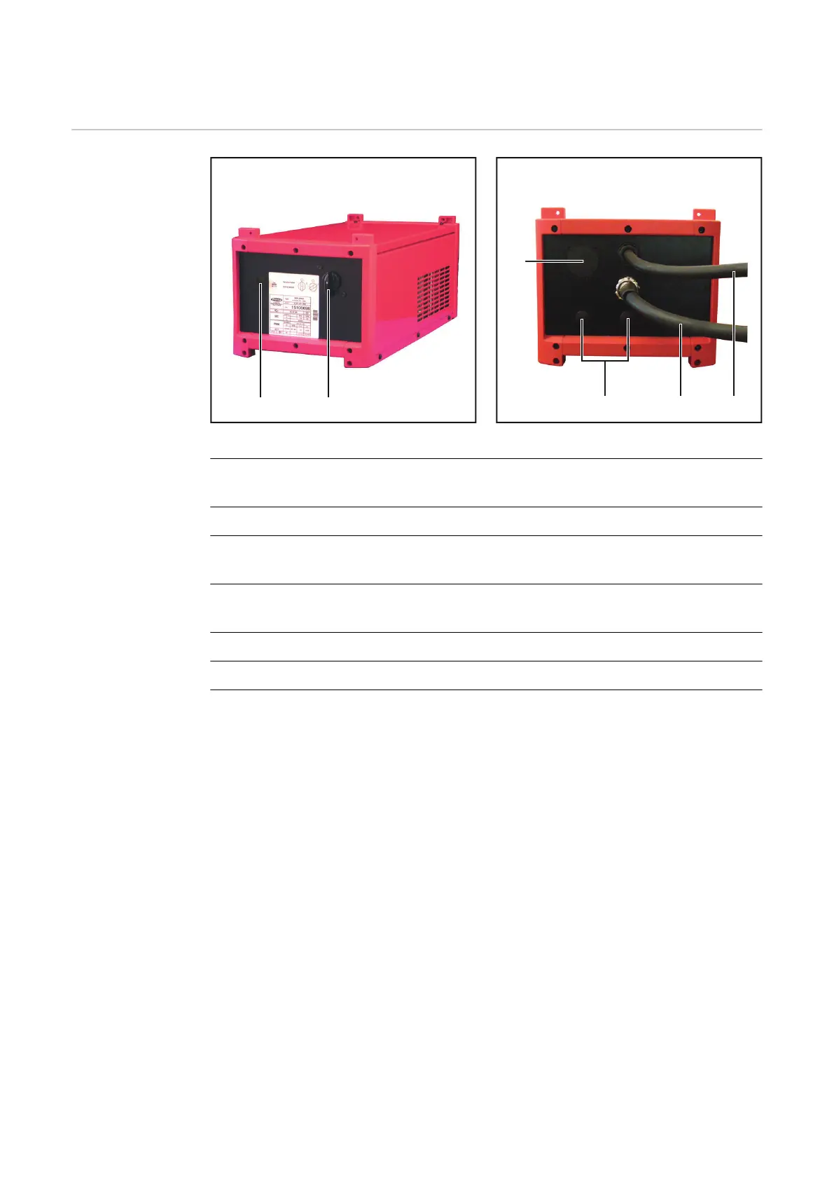
Control elements and connections
Controls and
connections,
versions 1 and 4
Front of TPS 2700 600/575 - 460 V and TPS
5000 480 - 455 V auto-transformers
Rear of TPS 2700 600/575 - 460 V and TPS
5000 480 - 455 V auto-transformers
(1) Main switch
central switch for turning all welding system components on and off
(2) Blanking cover
(3) Power source connection cable „OUTPUT 460 V (455 V) 50/60 Hz“
for supplying the power source with the transformed voltage.
(4) Mains cable „INPUT 600/575 V (480 V) 50/60 Hz“
for supplying the autotransformer with the mains voltage
(5) Blanking cover
(6) Blanking cover
36
 Loading...


