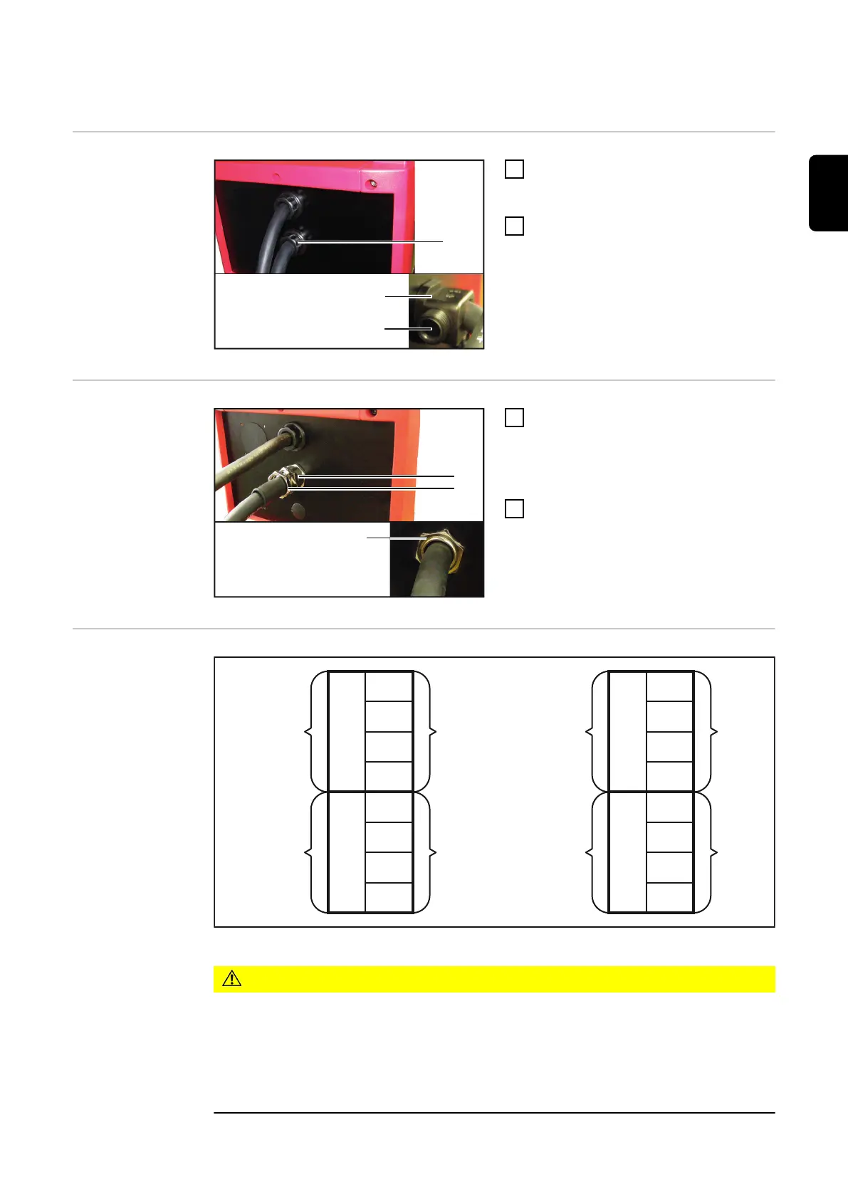
Fitting the mains cable to the auto-transformer
Securing the
mains cable in
the strain relief
device, versions
1 and 2
(1)
Inside strain relief device
(1)
(2)
1
Insert the auto-transformer mains
cable 220 mm into the strain relief
device (1)
2
Tighten the screw (2) for the mains
cable strain relief with an appro-
priate screwdriver, do not clamp
the cable
Fitting the mains
cable and strain
relief device,
versions 3 and 4
Inside strain
relief device
(4)
(3)
(3)
1
Screw the strain relief device (3)
and auto-transformer mains cable
to the rear of the auto-transformer
(hexagon nut - width across flats
30 mm)
2
Tighten screw on the strain relief
bracket (4)
Connecting the
auto-transfor-
mer mains cable
3
4
1
2
7
8
5
6
L3
PE
L1
L2
INPUT 480V
50/60Hz
L2
L3
PE
L1
OUTPUT 455V
50/60Hz
3
4
1
2
7
8
5
6
L3
PE
L1
L2
INPUT 600V/575V
50/60Hz
L2
L3
PE
L1
OUTPUT 460V
50/60Hz
Power source
Mains
Power source
Mains
Connecting the auto-transformer mains cable phase conductor
CAUTION!
Danger from operating the auto-transformer with only partially clamped phase
conductors.
This can result in serious damage to property.
▶
When connecting the auto-transformer connection cable, always make sure
that all phase conductors and the earth conductor (PE green) are clamped.
▶
Incorrect connection can permanently damage the device.
41
EN
 Loading...


