49
EN
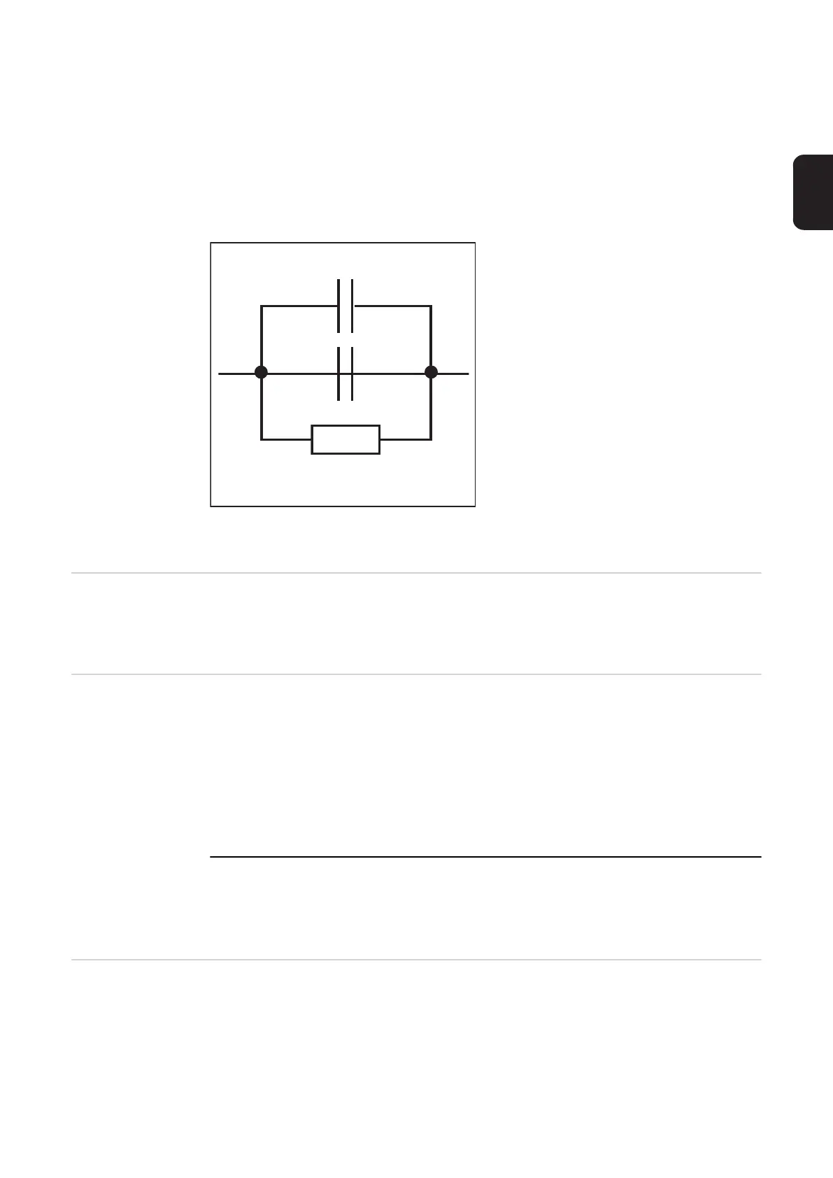
The use of an RC element is mandatory so that if the gas nozzle touches the workpiece
during welding,
- there are no excessive currents across the gas nozzle - welding current lead connec-
tion
- the welding process is not affected
If the gas nozzle makes contact, the short-circuit current flows for approx. 4ms until the RC
element capacitors are charged. To ensure contact by the robot control is always detected,
the current flow signal lasts 0.5 s longer than the short-circuit current..
RC element for connecting the welding current lead to
the gas nozzle
(1) Welding current lead
(2) Gas nozzle
Torch blow out If an additional solenoid valve for compressed air is installed in the robot feeder, it can be
controlled by the “Torch blow out“ command. The “Torch blow out“ signal is used to clear
the gas nozzle of dirt after cleaning the torch.
Source error re-
set
When a fault occurs, this remains until the robot control sends the “Source error reset“ sig-
nal to the power source. The reason for the fault must first however be rectified. As the sig-
nal level is controlled, it does not react to a rising edge. If the source error reset signal is
always HIGH, any error that occurs is reset immediately after it has been rectified.
IMPORTANT!
The “Welding start“ signal must not be on the robot, since the power source would
start welding again as soon as the fault is rectified.
If a non-programmed characteristic is selected, “no | PrG“ appears on the displays. The
robot control turns off the “power source ready“ signal. To reset, select an occupied pro-
gram location.
Job number Using this 8-bit signal, the welding operation is carried out with the welding parameters
saved under the selected job number. By selecting job number 0, the job can be selected
on the control panel.
(1)
C1: 2,2 µF / 160 V / 10 %
C2: 4,7 µF / 160 V / 10 %
R: 10 kOhm / 1 W / 10 %
(2)