37
EN-US
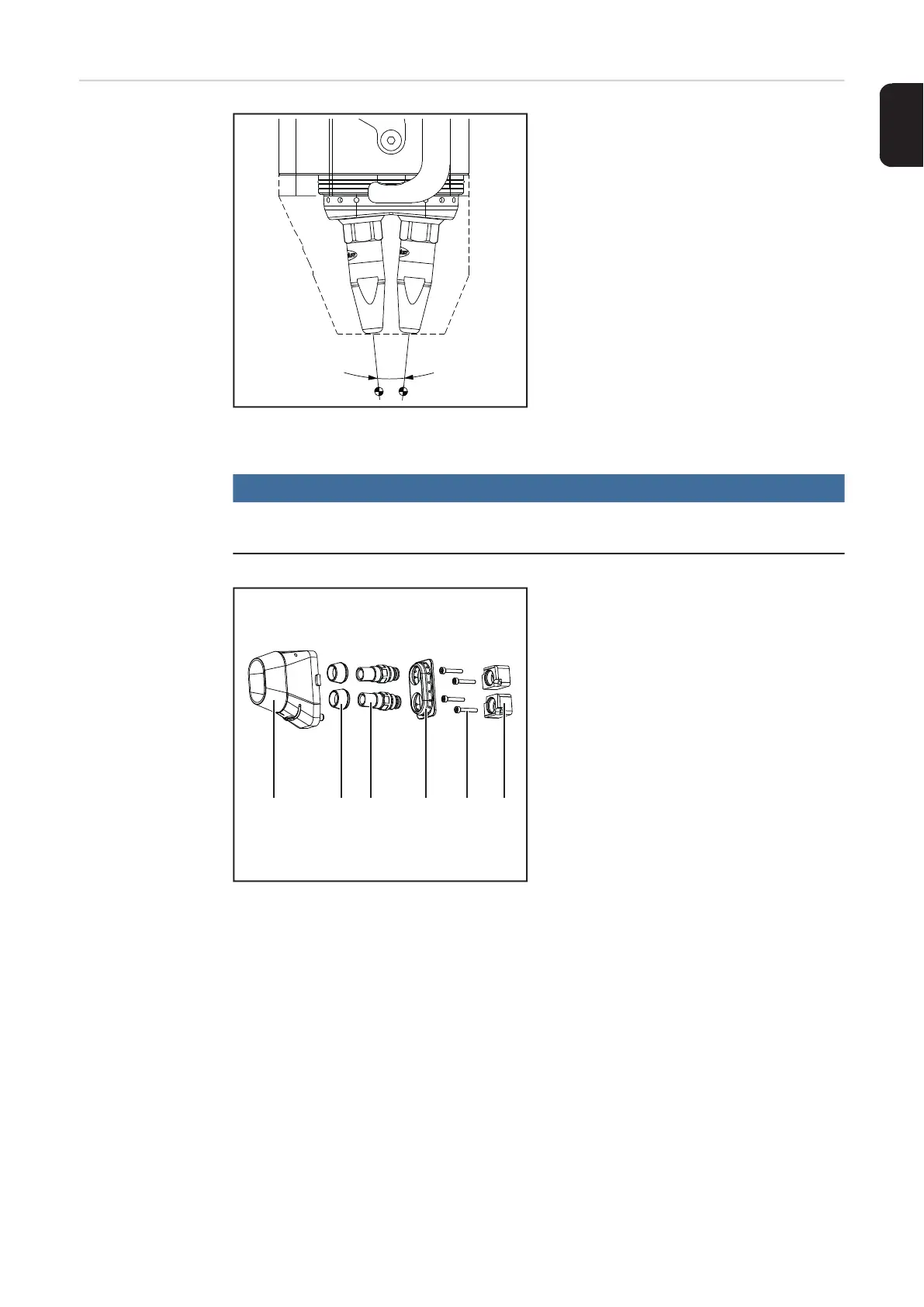
Tilt angle of the
contact tips
Example:
Tilt angle of the contact tips toward each other = 11.5°
Depending on the application, different tilt
angles of the contact tips toward each other
of 4°, 8° and 11.5° are available for the
TWIN welding torches.
Corresponding assembly components are
required for each angle:
4° OPT/i MTB TWIN 4.0° sym.
4,101,105,CK
8° OPT/i MTB TWIN 8.0° sym.
4,101,108,CK
11.5° OPT/i MTB TWIN 11.5° sym.
4,101,102,CK
NOTE!
The tilt angle-dependent dimensions of the welding torch can be found in the tech-
nical data from page 98.
The following assembly components are in-
cluded in the OPT/i MTB TWIN:
(1) 1 x gas nozzle
(2) 2 x insulating sleeve
(3) 2 x nozzle fitting
(4) 1 x gas distributor
(5) 4 x cylinder head screws M2.5 x 16
mm
(6) 2 x nozzle fitting holder

 Loading...


