42
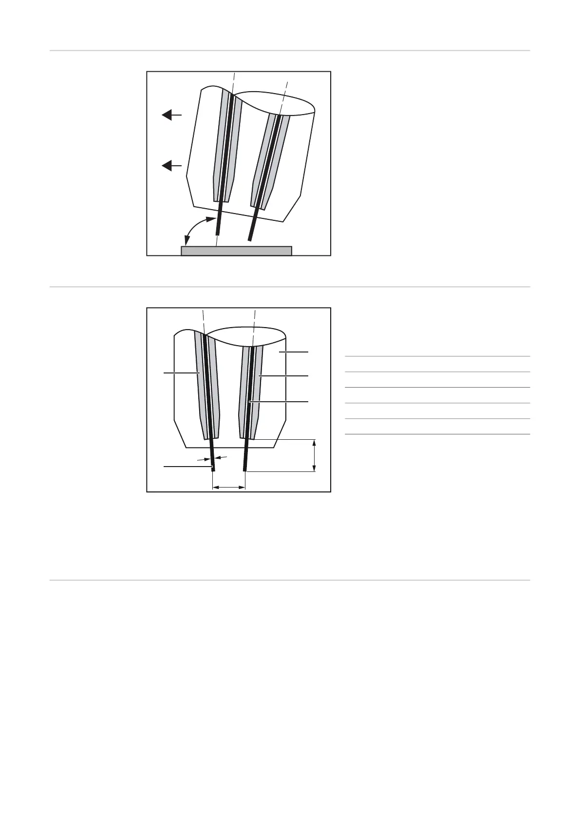
Work angle of the
welding torch
Work angle of welding torch neutral to slightly leading
Select the work angle of the welding torch
so that the lead wire electrode (= wire elec-
trode of the lead power source) is in a neu-
tral to slightly leading position.
approx. 90–100° for steel applications
approx. 100–115° for aluminum applicati-
ons
Stick out
Stick out (SO) and distance of the wire elec-
trodes depending on the diameter (D) of the
wire electrode:
(1) Wire electrode 1
(2) Contact tip 1
(3) Gas nozzle
(4) Contact tip 2
(5) Wire electrode 2
* The distance of the wire electrodes depending on the tilt angle of the contact tips
and the stick out can be found in the technical data from page 98.
TWIN mode The robot controls use the signals "Operating mode TWIN System Bit 0" and "Operating
mode TWIN System Bit 1" to define
- the lead and trail process line in TWIN mode
- the active process line in single wire mode
D [mm / inch] SO [mm / inch]
1.0 / 0.039 15 / 0.591
1.2 / 0.047 17 / 0.669
1.4 / 0.055 18 / 0.709
1.6 / 0.063 21 / 0.827

 Loading...


