41
EN-US
Welding Technology Aspects
Protective gas
shields for TWIN
welding process-
es
Gas control
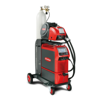
Set the same gas flow volume on both power sources.
The entire gas flow volume must be a total of approx. 25 - 30 l/min.
Example:
gas flow volume = 30 l/min
==> set power source 1 to 15 l/min and power source 2 to 15 l/min
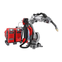
TWIN welding torch/TWIN mode:
both solenoid valves are switched
TWIN welding torch/single wire mode:
both solenoid valves are switched
Single welding torch with adapter (TXi interchangeable coupling optional):
one solenoid valve is switched
(solenoid valve for the power source selected by the robot controls)
Gas pre-flow/gas post-flow with TWIN welding torch:
the same value should generally be set on both power sources;
if the values are different, the larger value is automatically applied to both power sources.
Conducting R/L
comparison
IMPORTANT! The R/L comparison must be carried out separately for each power source.
R = welding circuit resistance [mOhm]
L = welding circuit inductivity [µH]
Material Protective gas shield
Non-alloyed and low-alloy steels ArCO
2
, ArO2 and ArCO
2
O
2
mixtures
CrNi steels, high-alloy steels ArCO
2
mixtures, proportion of active gas max.
2.5%
ArO
2
mixtures, proportion of active gas max. 3%
ArCO
2
He mixtures, proportion of active gas max.
xx%
Aluminum Ar (99.9%), ArHe mixtures
 Loading...
