45
EN-US
PMC TWIN / PMC
TWIN
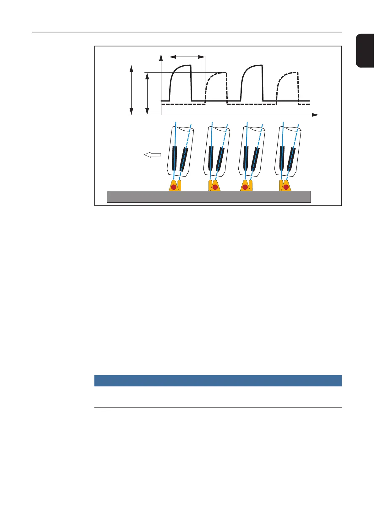
Welding current time curves and schematic representation of the material transition
P = phase shift
Time coordination of the power sources
The PMC processes of the two process lines are synchronized with one another. This
guarantees a stable, consistent tandem welding process.
The relative position of the pulse/droplet detachment is stored in the characteristic but can
also be freely selected.
Significantly different outputs at lead and trail wire electrode
The TPS/i TWIN welding system enables significantly different outputs or wire speeds to
be used, even during synchronized PMC tandem processes.
A significantly higher output is usually selected at the lead wire electrode than at the trail
wire electrode.
This results in:
- targeted heat input
- the cold parent material melts well
- exact recording of the root pass
- trail wire electrode fills up the weld pool
- extension of the gas release time (reduced proneness to porosity)
- high welding speed
NOTE!
The TWIN process PMC TWIN/PMC TWIN should generally be used for all welding
applications.

 Loading...


