EXAMPLE 2
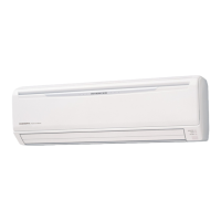
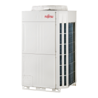
Fig.1 Outline of the system
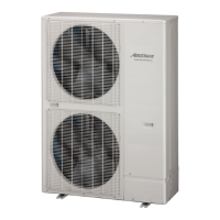
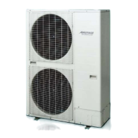
Outdoor
unit
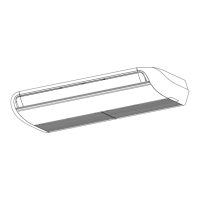
Indoor
unit 1
Indoor
unit 2
Indoor
unit 3
Indoor
unit 4
Indoor
unit 5
Room 1 Room 2 Room 3 Room 4 Room 5
Pipe length, L=70m
Height difference, H=20m
Design conditions:
Temperature ●
Indoor : 28°CDB / 20°CWB
Outdoor : 35°CDB
Pipe length : 70m ●
Height difference : 20m ●
(Outdoor unit upper side)
Selection of indoor unit
z
Room 1 Room 2 Room 3 Room 4 Room 5
Remark
A-1 Cooling heat load kW 8.0 1.7 1.7 0.8 0.8
A-2 Indoor unit models AUXA30 AUXB07 AUXB07 AUXB04 AUXB04
A-3 Rated capacity (TC
in
)
r
kW 9.0 2.2 2.2 1.1 1.1
See 7
A-4 Capacity at design temperature (TC
in
)
d
kW 9.7 2.4 2.4 1.2 1.2
See 7
A-5 Compensation coefcient of pipe length 0.86
See 6
A-6 Estimated capacity of indoor unit (TC
in
)
e
kW 8.3 2.1 2.1 1.0 1.0
(A-4) x (A-5)
A-7 Total rated capacity ∑(TC
in
)
r
kW 15.6
Sum of A-3
A-8 Total capacity at design temperature ∑(TC
in
)
d
kW 16.9
Sum of A-4
Preliminary selection of outdoor unit
z
Remark
B-1 Outdoor unit model 6HP : AJ
A54LALH
B-2 Rated capacity (TC
out
)
r
kW 15.5
See 2
B-3
Total rated capacity of indoor unit / Rated capacity of outdoor unit
∑(TC
in
)
r
/ (TC
out
)
r
% 100.6
(A-7) / (B-2)
B-4 Capacity at design temperature (TC
out
)
d
kW 16.4
See Fig.2 2)
B-5 Compensation coefcient of pipe length 0.86
See 6
B-6 Compensated capacity of outdoor unit (TC
out
)
c
kW 14.1
(B-4) x (B-5)
Decide system capacity
z
Remark
C-1 System capacity kW 14.1
Smaller one of
(A-8) and (B-6)
Calculate actual capacity of each indoor unit
z
Room 1 Room 2 Room 3 Room 4 Room 5
Remark
Actual capacity of each indoor unit kW 8 .1 2.0 2.0 1.0 1.0
(C-1) x (A-3) / (A-7)
- (02 - 11) -
MODEL
SELECTION
MODEL
SELECTION
 Loading...
