POWER SUPPLY CABLE WIRING4-2.
POWER SUPPLY CABLE SPECIFICATIONS
Use a separate power supply for the outdoor unit and indoor unit.
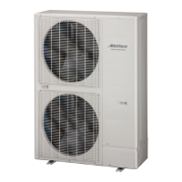
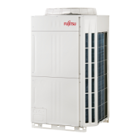
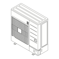
Outdoor unit
z
Model
Recommended cable size
(mm
2
)
Fuse capacity
(A)
Breaker for
leakage current
Remarks
Power cable Earth cable
AJ
A40LALH 6 4 32
30mA 0.1sec
or less
230V~ 50Hz
2Wire + ground
AJ
A45LALH 6 4 32
AJ
A54LALH 6 4 32
Select wire size base on the value of MCA and TOCA. In the table of "3.OUTDOOR
●
UNITS",example of wiring specication for outdoor unit is given.
Select circuit breaker for outdoor unit based on the value of MCA of "3.OUTDOOR UNITS".
●
The breaker should not operate when starting current is generated.
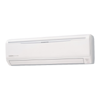
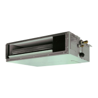
Indoor unit
z
Model
Recommended
cable size (mm
2
)
Fuse capacity
(A)
Breaker for
leakage current
Remarks
All models 2.5 20 Refer to Table B
230V~ 50Hz
2Wire + ground
Refer to the table for the breaker specications of each installation condition. Perform the
power crossover wiring within the range of the same refrigerant system.When the crossover
wiring is done, make a connection for indoor unit to satisfy conditions Table A and Table B
below.
Table A. Current breaker requirements
Model
MCA
(A)
Fuse capacity
(A)
All models *1 20
MCA : Minimum Circuit Ampacity
*1 : Refer chapter4 3.ELECTRIC CHARACTERISTICS
When the power crossover wiring is done, make it so that the total of the MCA of the
connected indoor units does not exceed the 15 A.
If the capacity of connected indoor units exceeds the upper limit, either add breakers or use a
breaker with a greater capacity.
Table B. Earth leakage breaker requirements
Breaker capacity Maximum connectable indoor unit
30 mA, 0.1 sec or less 9 or less
Select cable size base on the value of total MCA of the indoor units connected. and if
●
necessary divided the system which the total MCA of the indoor units connected must be
smaller than 15 (A). The indoor units shall be connected up whthin refrigerant system.
In order to be inuenced of a breaker stop, please divide a power supply circuit for every
●
refrigerant system.
Please attach at least one breaker per refrigerant system.
●
Please design the power supply circuit to keep the voltage drop within 2%.
●
- (06 - 46) -
SYSTEM
DESIGN
SYSTEM
DESIGN
 Loading...
