WIRING SYSTEM OUTLINE
Outdoor unit power supply cable
1ø 50Hz 230V
Remote controller cable (2 line) non-polar 2 core cable,
seathed cable 0.33-1.25mm
2
*Shilded cable might be
required in accordance with the regional standard
Transmission cable
Non polar 2core,
shielded Level4,
0.33mm
2
USB adaptor
(eld supplied)
USB
adaptor
USB
adaptor
USB
adaptor
Network
convertor
UTY-VGGXZ1
Central
Remote
Controller
UTY-ABGX
Network
convertor
for
L
ON
W
ORKS
®
UTY-VLGX
Network convertor
UTY-VGGXZ1
Network convertor
UTY-VGGXZ1
Signal Amplier
UTY-VSGX Z1
Web Monitoring Tool
Internet
or
Public Telephone Line
Transmission line
line is non-polar 2-conductor.
Required in case of follows
Transmission line 500m or more
Number of unit 64 or more
Can be connect anywhere
on transmission line
(Field supplied)
(Field supplied)
External switch controller cable
Polar 3 core, shielded, 0.33mm
2
Max length 25m
Remote controller cable
Polar 3 core, 0.33mm
2
System without remote controller
Together with Touch panel controller, it is
possible to build non remote controller system.
Group Remote Controller connection cable
Polar 3 core, shielded, 0.33mm
2
,
Max length total 100m
Touch Panel
Controller
IR Receiver Kit
Cassette type indoor unit can be
controlled with wireless remote controller
IR receiver unit
Duct type indoor unit
can be controlled with
wireless remote controller.
Service Tool
Big multi system
Card key
Single system
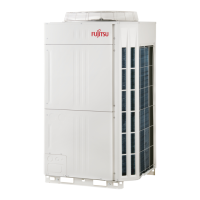
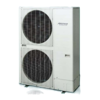
Outdoor unit
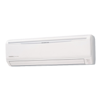
Indoor unit
(Cassette)
Indoor unit
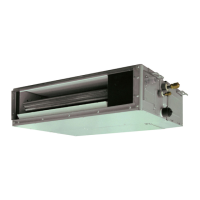
(Duct)
System
Controller
Touch Panel
Controller
Group Remote
Controller
Wired Remote
Controller
Wired Remote
Controller
Simple Remote
Controller
Central Remote
Controller
Simple Remote
Controller
Transmission line
Module link
Remote controller
line
Signal line
(single system)
USB cable
Ethernet
L
ON
W
ORKS
®
Network
Wireless Remote
Controller
External Switch
Controller
IR Receiver unit
(VRF system side)
(Monitoring side)
(Monitoring side)
(Monitoring side)
BACnet® Gateway
BACnet®
L
ON
W
ORKS
®
L
ON
W
ORKS
®
Network
BACnet®
BACnet® Operator
Workstation (B-OWS)
NW1
NW2 *2
NW3 *2
NW4 *2
1ø 50Hz 230V
1ø 50/60Hz 220-240V
1ø 50/60Hz 220-240V
1ø 50/60Hz 100 to 240V
1ø 50/60Hz 100 to 240V
1ø 50Hz 230V
1ø 50Hz 230V
Indoor unit power supply cable
50Hz 230V ~
1ø 50/60Hz 220-240V
1ø 50/60Hz 220-240V
Disconnect switch might be required in accordance with the regional standard.
(Remote /
Monitoring
side) *1
(Remote /
Monitoring
side) *1
Remote controller line (3 wire)
Maximum 16 units can be controlled
Total wiring length : Max 500m
Remote controller line (2 wire)
Maximum 16 units can be controlled
Total wiring length : Max 500m
Case of UTY-ALGX
*1: Option is necessary.
*2: Can not be used.
- (06 - 45) -
SYSTEM
DESIGN
SYSTEM
DESIGN
 Loading...
