EXAMPLE OF PIPING DESIGN2-6.
REFRIGERANT SYSTEM 1
b
a
a1 b1 c1 d1 e1 f1 g1
c d e f g h
1 2 3 4 5 6 7 8
BP1 BP2 BP3 BP4 BP5 BP6 BP7
Outdoor
unit
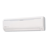
Indoor
unit
(18.2kW) (15.4kW) (13.2kW) (11.0kW) (8.8kW) (6.6kW) (4.4kW)
(2.8kW) (2.2kW) (2.2kW) (2.2kW) (2.2kW) (2.2kW) (2.2kW) (2.2kW)
(2.2kW)
Indoor
unit
Indoor
unit
Indoor
unit
Indoor
unit
Indoor
unit
Indoor
unit
Total cooling capacity of indoor units
connected downwards to the pipe.
Indoor
unit
System conguration
z
(Indoor units)
1 2 3 4 5 6 7 8
Total Capacity
(kW)
Model name ARXD09 ARXD07 ARXD07 ARXD07 ARXD07 ARXD07 ARXD07 ARXD07
18.2
Capacity (kW) 2.8 2.2 2.2 2.2 2.2 2.2 2.2 2.2
System conguration
z
(Outdoor unit)
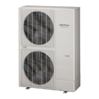
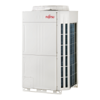
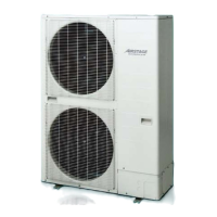
Outdoor unit
Model name AJ
A54
Capacity (kW) 15.5
Capacity ratio
z
(Total indoor unit capacity) / (Total outdoor unit capacity)
= (18.2) / (15.5) = 117.4% (Within 50% to 130%)
Selection of branch kit
z
Branch
point No.
Model
BP1 UTP-AX090A
BP2 UTP-AX090A
BP3 UTP-AX090A
BP4 UTP-AX090A
BP5 UTP-AX090A
BP6 UTP-AX090A
BP7 UTP-AX090A
Model Q'ty
UTP-AX090A 7
- (06 - 23) -
SYSTEM
DESIGN
SYSTEM
DESIGN
 Loading...
