13
Interlace Polarity: Set interlace polarity.
ITRP (0-4092 Step4): Enter interlace pulse position.
ITRW (0-4092 step4): Enter interlace pulse width.
Sampling Rate: Display sampling rate. Fixed at “15 seconds”.
Compress Type (viewer): Set compress type (viewer).
Color Bit: Display and set Color Bit.
Change Pump Current: Set pump current. Fixed at “0.5 mA”.
Video Clock Polarity: Set video clock polarity. Fixed at “Through”.
Counter Clock Selection: Select counter clock selection. Fixed at “49 MHz”.
VCO Clock Hold: Sets VCO clock hold.
Red Gain (0-255): Enter red gain.
Green Gain (0-255): Enter green gain.
Blue Gain (0-255): Enter blue gain.
Red Offset (0-255): Enter red offset.
Green Offset (0-255): Enter green offset.
Blue Offset (0-255): Enter blue offset.
Black Level (0-255): Enter black level.
Equipment Category: Enter equipment category.
Board Name*: Enter board name for corresponding channel.
Note*: Enter note.
Note: Offset, Phase and Color Bit change with the length of the antenna cable.
*Marked Items: For easy identification of input source, enter Equipment Category, Brand,
Type No., and Data Name.
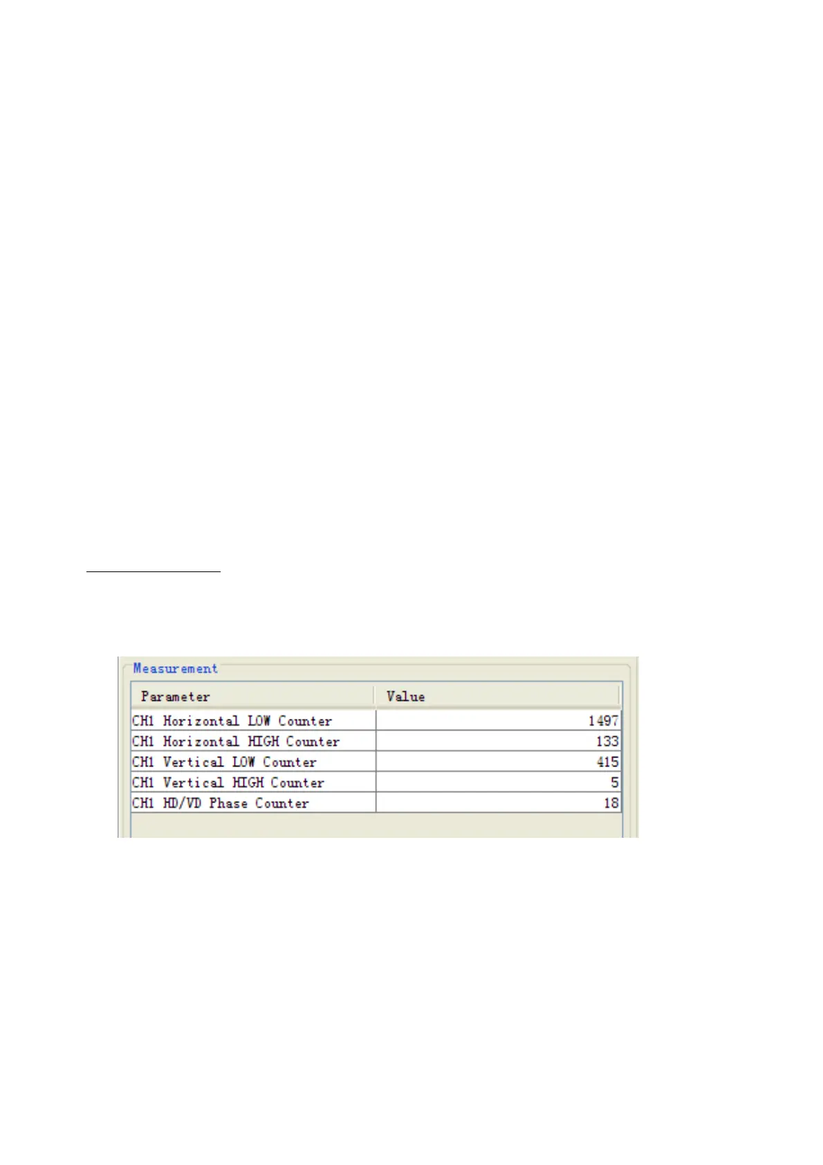
Measurement Box
The Measurement Box is located on the left side of the Information Area. The LOW
Horizontal and Vertical counter should be higher than the HIGH counter. If, reversely, the
HIGH counter is higher than the LOW counter, it is possible that the SYNC Polarity
settings are adjusted incorrectly.