GT7 Terminal
Configuration
www.gantner.com
HB_GT7-2x00-3x00--EN_12
71
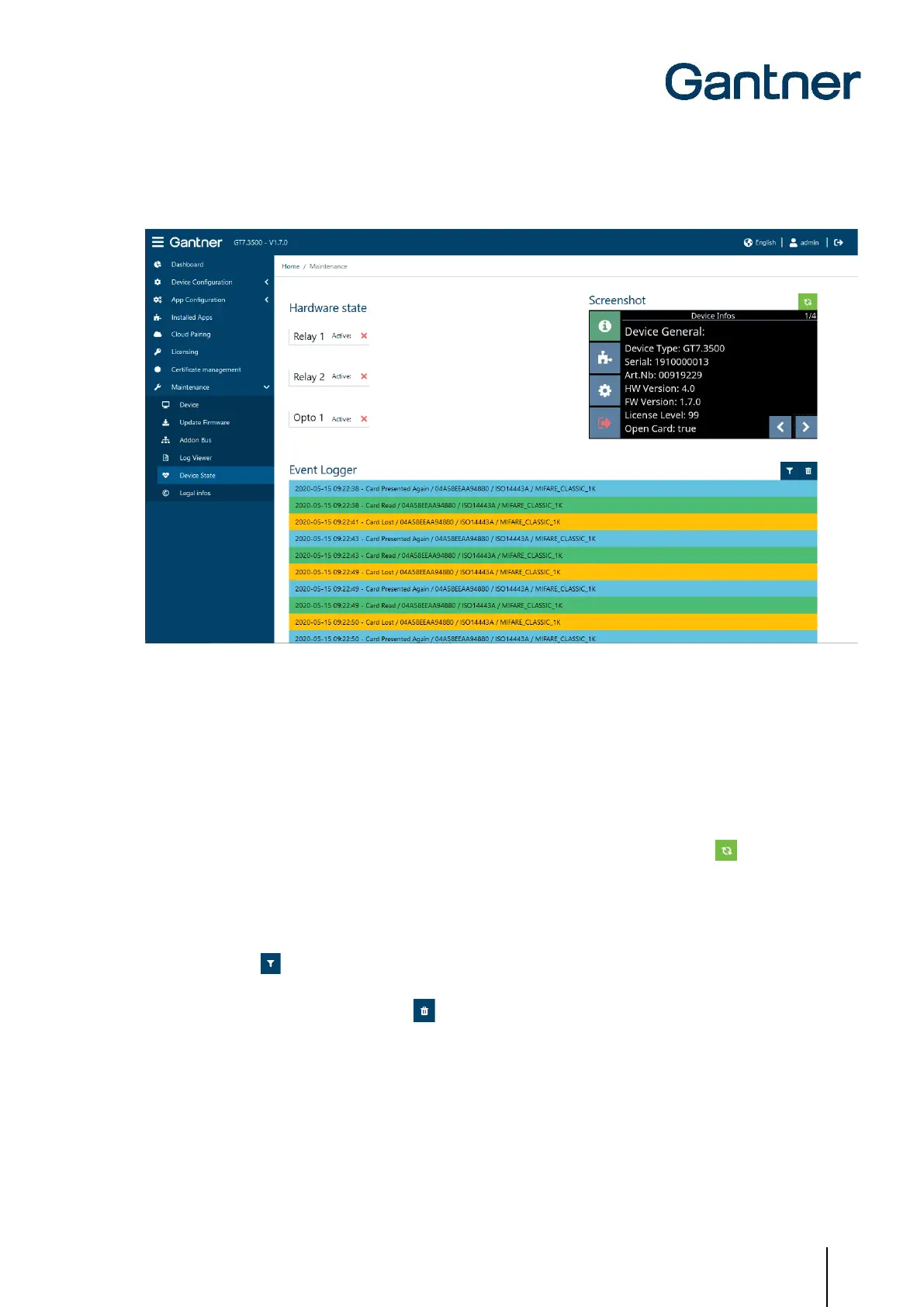
5.6.24 Device State
Figure 5.51 – GT7 terminal web interface – Device State
Depending on the model, a GT7 terminal has either one or two digital relay outputs and one digital optocoupler
input. These can be used to receive status information and/or for control. The state of these inputs and outputs is
displayed here under “Hardware state”. The inputs and outputs do not need to be used. In the example shown, they
are inactive.
To the right of hardware state is the screenshot function for the GT7 terminal.
► To take a screenshot of the screen currently displayed on the terminal, press the refresh button.
Below that is the Event Logger. Here, the live events occurring on the device are displayed.
► When an event occurs on the GT7 terminal (e.g., data carrier read) or when the optocoupler input state or one
of the relay states changes, a corresponding entry is displayed.
► The filter icon displays all event types. By clicking on these events, they can be switched between active
(green) and inactive (red). Only the green events are shown in the list.
► To clear the list, click on the trash icon .
 Loading...