G100 Instruction Manual
• 8 Binary Inputs (DI), wetted internally from main unit power supply circuit using single common (positive
voltage through external contacts). The binary inputs are individually isolated internally.
• 4 Binary Outputs (DO), isolated, as N.O. (Normal Open) single contact
• 4 DC Analog Input (AI) channels, +5V DC/ 20mA
The G100 device has 3 noticeable side panels for operation.
The names of each side panel as referenced in this document assume a G100 being positioned
vertically.
Top Panel
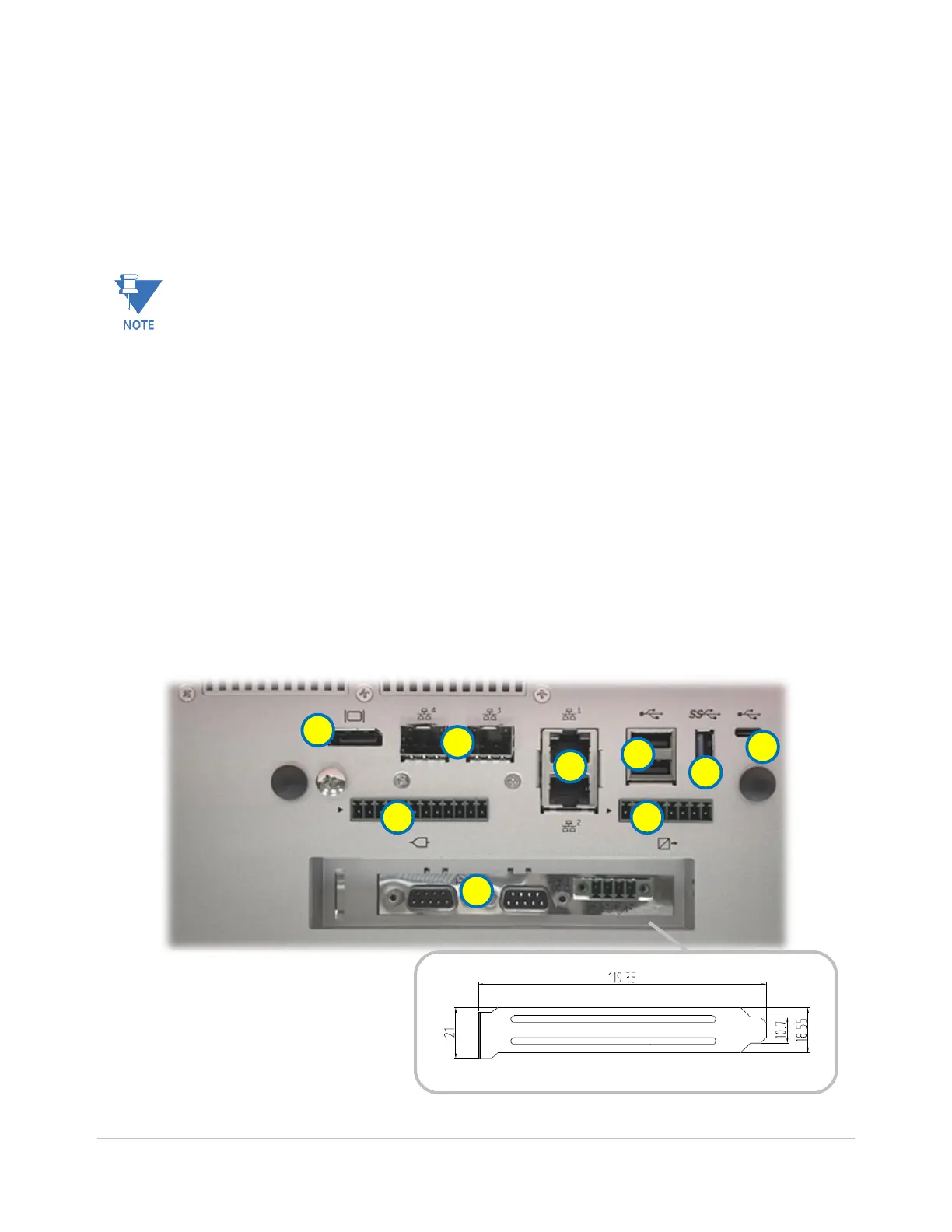
The top panel of the G100 provides access to:
1. 1x DP display port
2. 2x TP Ethernet ports with LED indications (labelled 1, 2)
3. 2x SFP Ethernet ports (labelled 3, 4)
4. 2x USB2 ports
5. 1x USB3 port
6. 1x USB-C port (future, currently not used)
7. 4x Analog Input (AI) connections (12 pin connector)
8. 4x Binary Output (DO) connections (8 pin connector)
9. D.20 HDLC connections, with LED indications (optional, in PCIe slot)
Figure 1: G100 Top Panel

 Loading...

