EasyManuals Logo

GE Multilin G100 User Manual

GE Multilin G100
70 pages
To Next Page IconTo Next Page
To Previous Page IconTo Previous Page
Page #37 background imageLoading...
Page #37 background image
G100 Instruction Manual
38 994-0155-1.00-1 GE Information
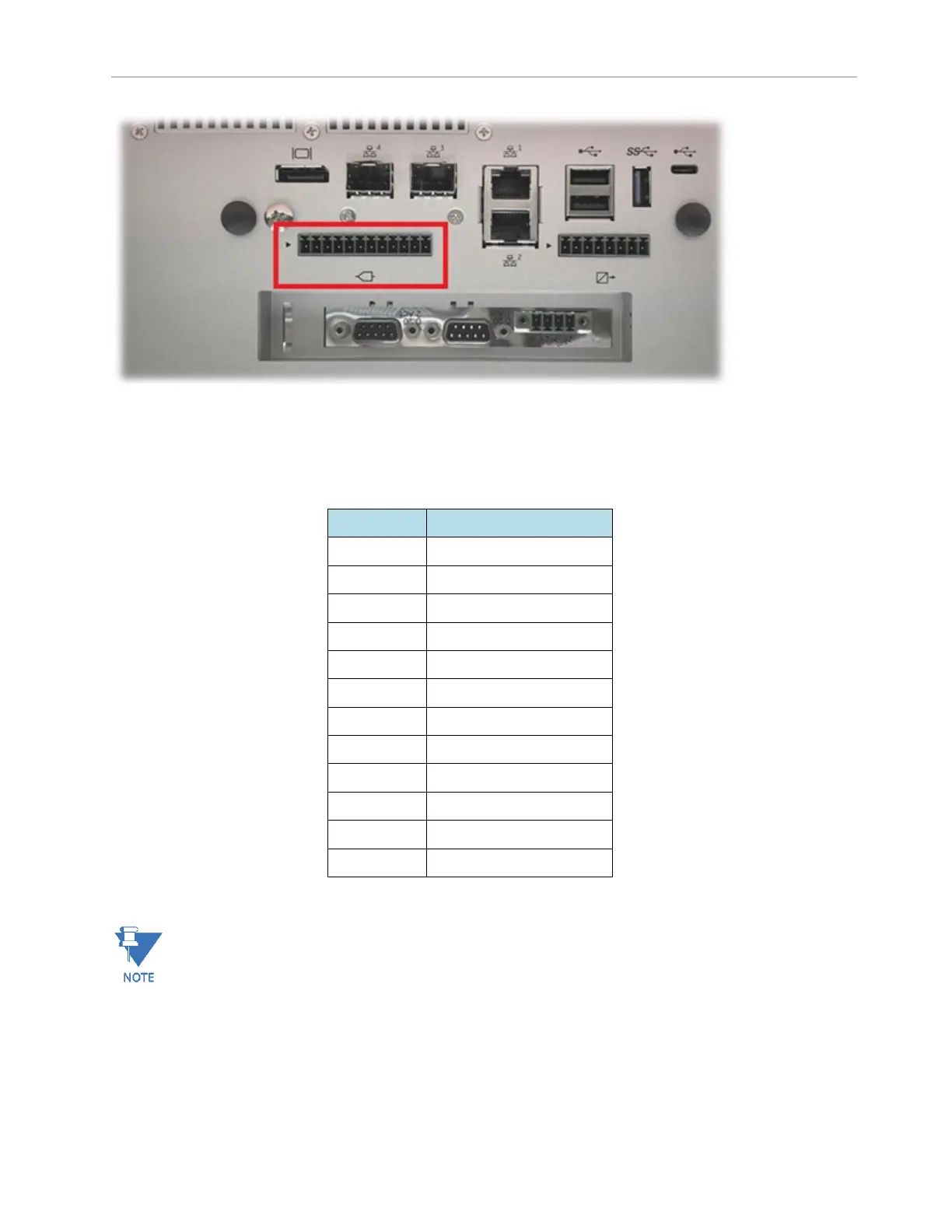
The small arrow on the left indicates PIN 1.
Table 6: GPIO AI connector pin assignments
PIN NO.
DESCRIPTION
1 (arrow)
A_VIN0+/IIN0 +
2
A_VIN0 -
3
AGND_ISO_CHS
4
A_VIN1+/IIN1 +
5
A_VIN1 -
6
AGND_ISO_CHS
7
A_VIN2+/IIN2 +
8
A_VIN2 -
9
AGND_ISO_CHS
10
A_VIN3+/IIN3 +
11
A_VIN3 -
12
AGND_ISO_CHS
In the pin description, ā€œ_CHSā€ is the shield connection for each AI channel (all CHS are common wired
internally).
The jumpers for Voltage or Current input selection are located on the GPIO internal board and their settings are
as follows:

Table of Contents

Questions and Answers:

Question and Answer IconNeed help?

Do you have a question about the GE Multilin G100 and is the answer not in the manual?

GE Multilin G100 Specifications

General IconGeneral
BrandGE
ModelMultilin G100
CategoryGateway
LanguageEnglish

Related product manuals