42 994-0155-1.00-1 GE Information
5
VDC1 -
VDC1 -
6
OPEN
7
D.20 Channel 2 TX/RX -
D.20 Channel 1 TX/RX -
OPEN
8
VDC2 +
VDC2 +
9
VDC2 -
VDC2 -
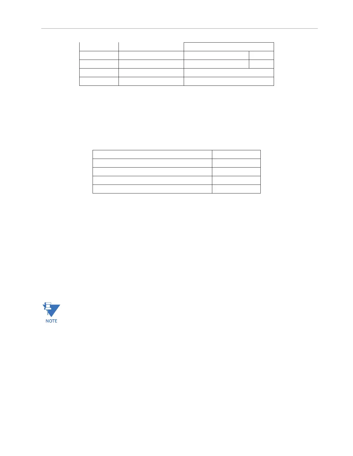
End of link termination is required at each end of the D.20 Link and is critical for proper operation. The D.20
HDLC PCIe card has two relays which control the End of Link termination, one for each D.20 Channel. Refer to
Table 2: Default D.20 Relay settings. End of Link termination settings are software controlled and are accessible
through the Settings GUI on your G100. Refer to SWM0101 for further details on configuration.
Table 9: Default D.20 Relay settings
End of Link termination on channel 1
End of Link termination on channel 2
D.20 channel 1 to D.20 port B connection
D.20 channel 2 to D.20 port B connection
Supplying power through the D.20 Link
Power is typically supplied to peripheral devices directly through the WESTERM boards or inject power into the
D.20 link using the D.20 DC Interface module (520-0154). However, with the D.20 HDLC PCIe card the Power
Pass Through connections can be utilized to inject power into the D.20 link to supply power to peripheral
devices through the D.20 ports.
One or two independent power supplies can be connected to DC Supply 1 (VDC1) and DC Supply 2 (VDC2). DC
Supply 1 (VDC1) is connected through to pins 4 and 5 on both D.20 ports (DB9 connector), respectively DC
Supply 2 (VDC2) is connected to pins 8 and 9.
The DC supply load on the D.20 port by the peripheral link must not to exceed 3.5A and 20 -60 VDC
The Power Pass Through connections are protected to 3.5A
 Loading...


