52 994-0155-1.00-1 GE Information
The cables must be shielded and the shield of each RS-485 cable section should be grounded at one end only.
This prevents circulating currents and can reduce surge-induced current on long communication lines.
Signal ground on pin4 is to be considered different then shield on cable.
When creating custom cables, it is recommended to only wire the required pins.
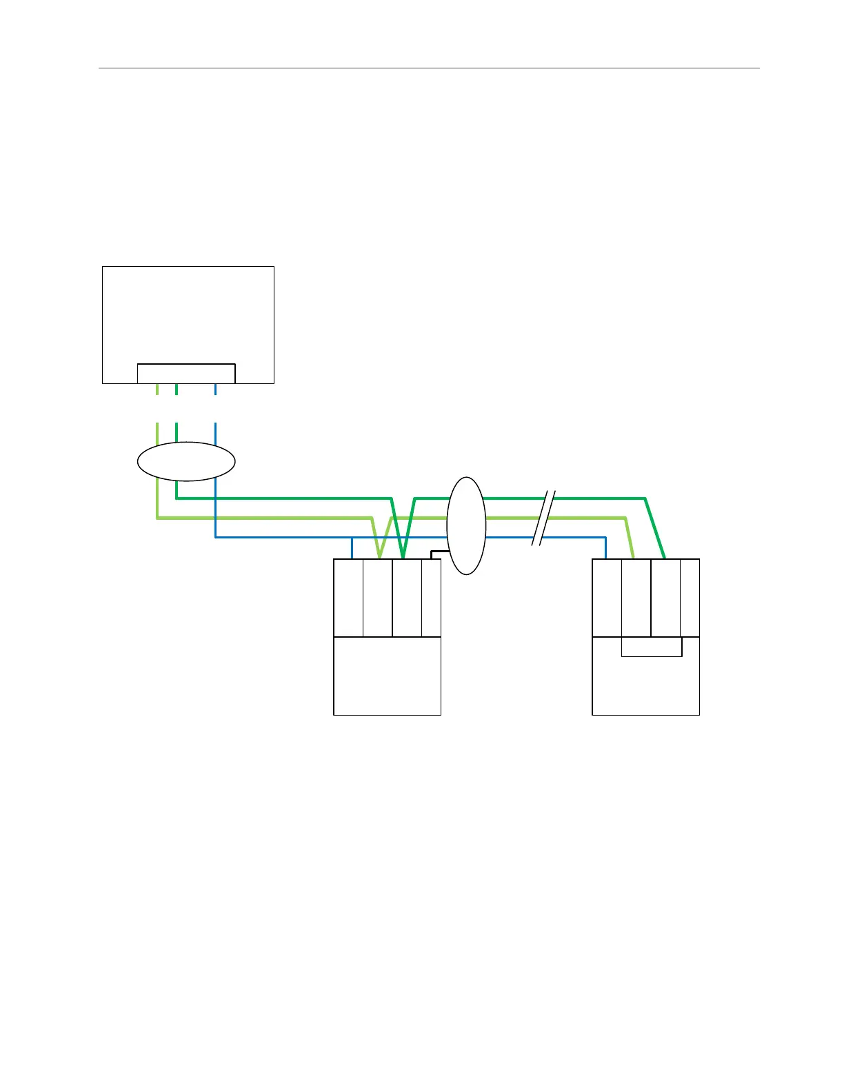
The following diagram illustrates how to wire the G100 units using RS485 2-wire.
Figure 9: G100 connection using RS485 2-wire
G100
Serial Port
s
RS485/2w/term in
RJ45 port 2
1 2
4
Ground shield at
G100 end only
Shielded
Cat5 +
Ground shield at
one end only
Shielded
Twisted
IED #1 IED
#n
RS485 2w
COM
C
- +
G
N
D
RS485 2w
COM
C
- +
G
N
D
Te rm enbl
Default Serial Maintenance port (port 4, RS232)
When running the Factory Default configuration, G100 has one serial maintenance port enabled, which is
always allocated to Port 4.
This maintenance port allows users to perform the following workflows:
• Intercept POST and access UEFI settings (useful when a KVM is not connected to G100)
• Access Shell for maintenance actions after the applications started
The following documents provide details for each workflow:

 Loading...

