EasyManuals Logo

GE Multilin G100 User Manual

GE Multilin G100
70 pages
To Next Page IconTo Next Page
To Previous Page IconTo Previous Page
Page #33 background imageLoading...
Page #33 background image
G100 Instruction Manual
34 994-0155-1.00-1 GE Information
The DI voltage supply is the same as the G100 Power Supply: 12/24/48 VDC, with each DI channel consuming
typically 5mA.
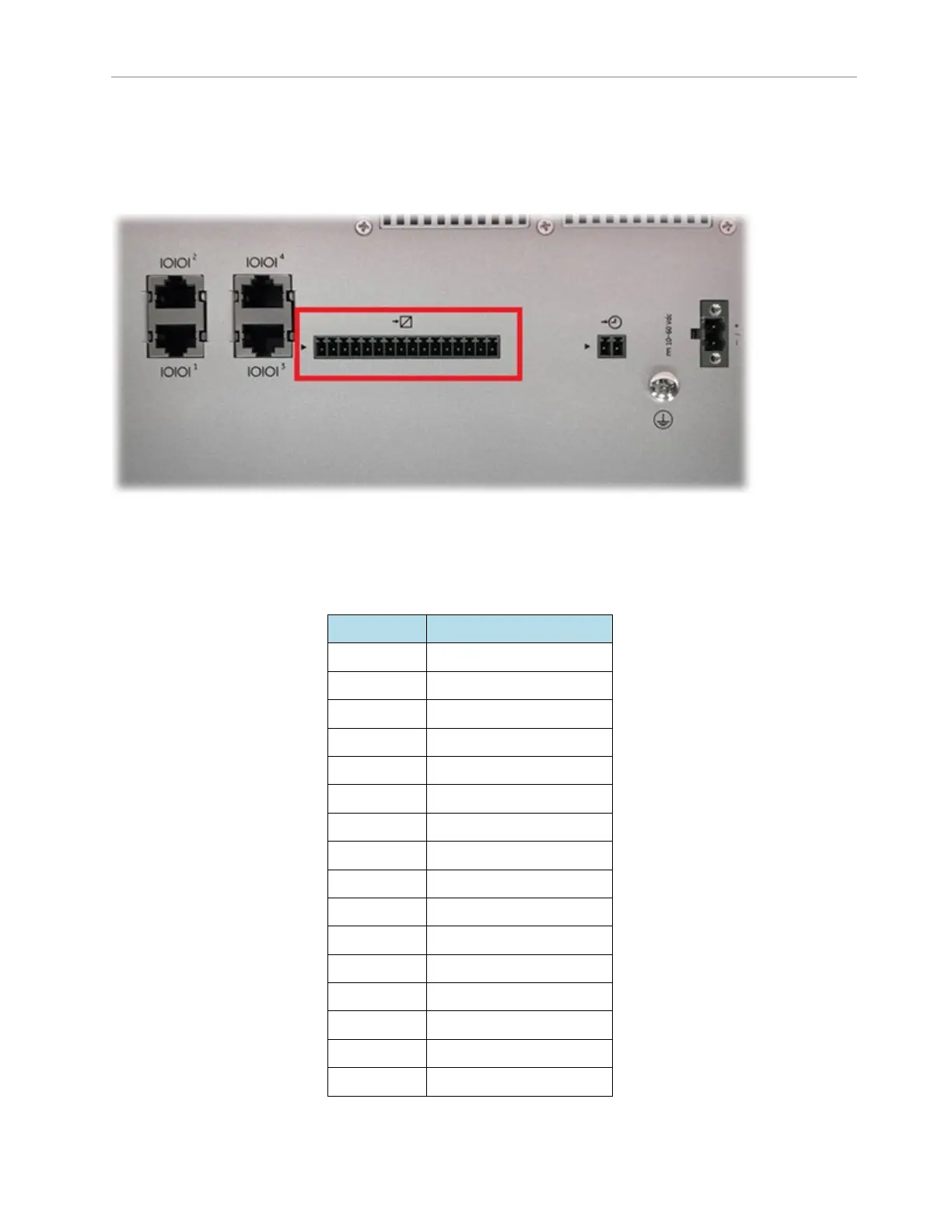
DI wiring is via a pluggable connector, pitch 3.5mm x 16 pins, located on the bottom side panel:
The small arrow on the left indicates PIN 1.
Table 4: GPIO DI connector pin assignments
PIN NO.
DESCRIPTION
1 (arrow)
DI_1
2
DI_COM (+)
3
DI_2
4
DI_COM (+)
5
DI_3
6
DI_COM (+)
7
DI_4
8
DI_COM (+)
9
DI_5
10
DI_COM (+)
11
DI_6
12
DI_COM (+)
13
DI_7
14
DI_COM (+)
15
DI_8
16
DI_COM (+)

Table of Contents

Questions and Answers:

Question and Answer IconNeed help?

Do you have a question about the GE Multilin G100 and is the answer not in the manual?

GE Multilin G100 Specifications

General IconGeneral
BrandGE
ModelMultilin G100
CategoryGateway
LanguageEnglish

Related product manuals