G100 Instruction Manual
Initial inspection
After unpacking the products, you should inspect it for visible damage that could have occurred during shipping
or unpacking. If damage is observed (usually in the form of bent component leads or loose socketed
components), contact GE Technical Support for additional instructions. Depending on the severity of the damage,
it may be necessary to return the product to the factory for repair.
DO NOT apply power to the product if it has visible damage!
Doing so may cause further, possibly irreparable damage, as well as introduce a fire or shock hazard.
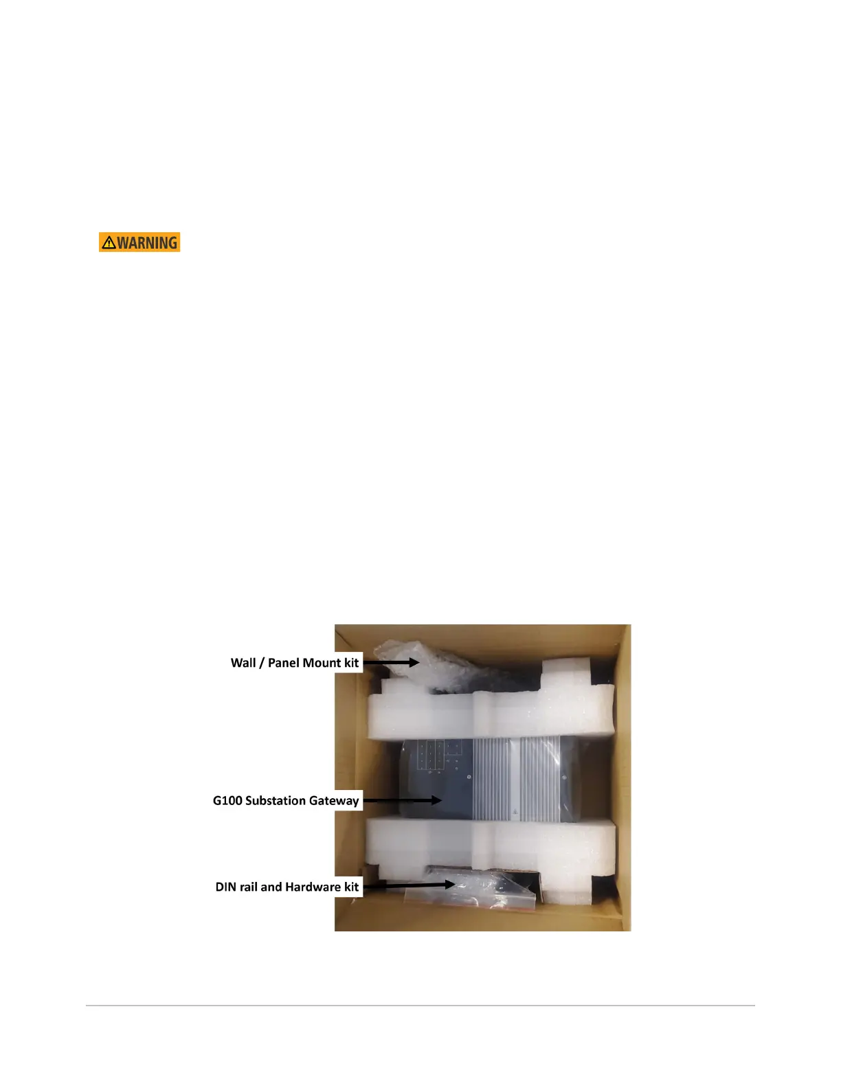
The G100 shipment will include the following:
• G100 Substation Gateway
• Wall / Panel mounting kit
• Wall / panel mounting bracket (quantity 2)
• DIN rail and Hardware kit
• DIN Rail (quantity 1)
• Screws (quantity 6)
• Analog DC Input (AI) connector (quantity 1)
• Binary Input (DI) connector (quantity 1)
• Binary Output (DO) connector (quantity 1)
• Power input connector (quantity 1)
• IRIG-B input connector (quantity 1)

 Loading...

