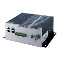
G100 Instruction Manual
Tables
Table 1: Warning symbols that may appear on the G100 and in this manual ....................................................................... 13
Table 2: Informational symbols that appear on the G100 and in this manual ....................................................................... 13
Table 3: G100 Order Code ................................................................................................................................................................................ 18
Table 4: GPIO DI connector pin assignments .......................................................................................................................................... 34
Table 5: GPIO DO connector pin assignments........................................................................................................................................ 36
Table 6: GPIO AI connector pin assignments .......................................................................................................................................... 38
Table 7: GPIO AI Voltage / Current selection jumper ........................................................................................................................... 39
Table 8: D.20 Port A and B pin out and configuration options ........................................................................................................ 41
Table 9: Default D.20 Relay settings ............................................................................................................................................................ 42
Table 10: D20A Analog Input Module Compatibility ............................................................................................................................ 43
Table 11: D20S Status Input Module Compatibility .............................................................................................................................. 44
Table 12: D20K Control Output Module Compatibility ........................................................................................................................ 44
Table 13: D20C Combination Input/Output Module Compatibility ............................................................................................... 45
Table 14: Repeater/Splitter Compatibility ................................................................................................................................................. 45
Table 15: Single D.20 terminated, Single Link - Default settings ................................................................................................... 46
Table 16: Dual D.20 link terminated – Default settings ...................................................................................................................... 47
Table 17: Single D.20 link, redundant LAN - Default settings .......................................................................................................... 48
Table 18: Redundant D.20 link, redundant LAN - Default settings ............................................................................................... 49
Table 19: RJ45 Pin outs for Serial Port Signals ....................................................................................................................................... 50
Table 20: SFP modules supported by the G100 ................................................................................................................................... 55
Table 21: Ethernet cables required by the G100 ................................................................................................................................... 56
Table 22: IRIG-B input connector pin assignments .............................................................................................................................. 56
Table 23: IRIG-B input signal selection TTL/RS-232 ............................................................................................................................. 57

 Loading...