P74x/EN OP/N
(OP) 5-
1. OPERATION OF INDIVIDUAL PROTECTION FUNCTIONS
The following sections detail the individual protection functions.
Note however that not all the protection functions listed below are applicable to every relay.
1.1 Busbar Biased Current Differential Protection
The primary protection element of the P74x scheme is phase segregated biased current
differential protection. The technique used is purely numerical and uses nodal analysis
throughout the scheme, on a per zone and per scheme basis. The analysis is carried out in
the central unit therefore communication between the central unit and all peripheral units is
essential. This is achieved via a direct optical connection utilising a 2.5 Mbits/sec data rate.
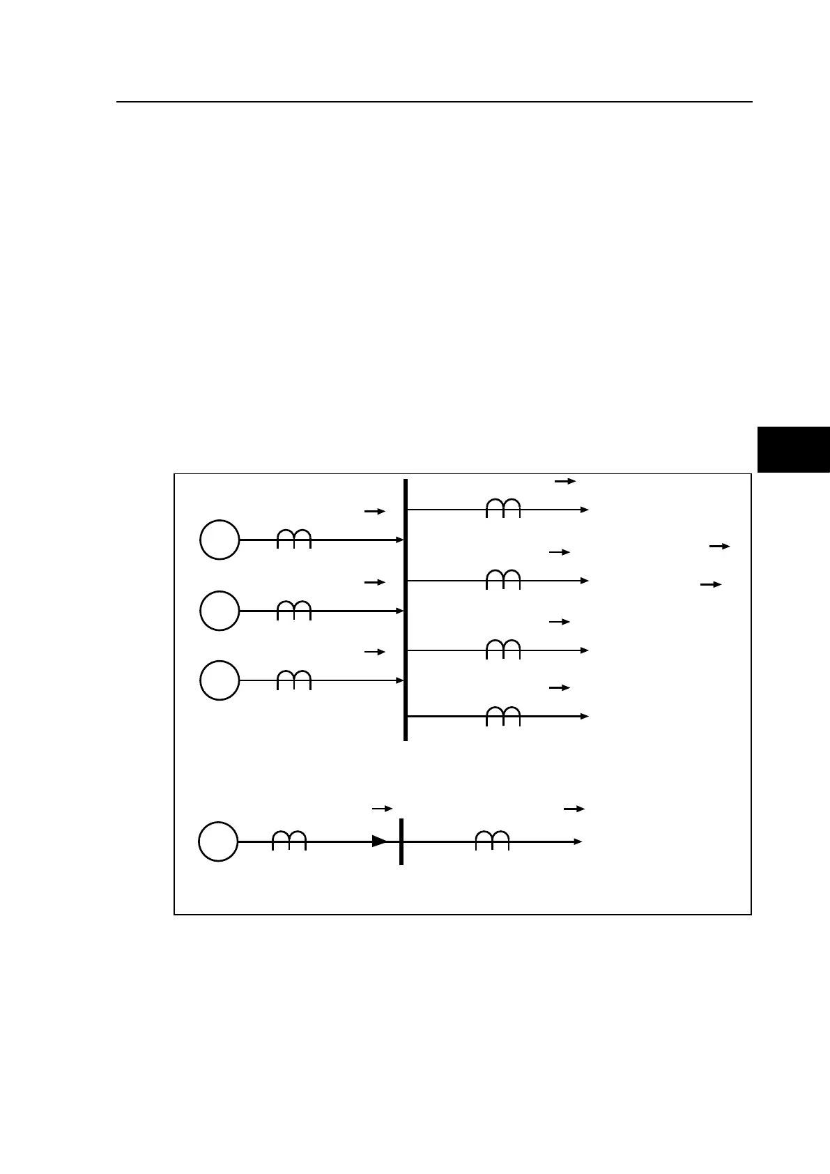
1.1.1 Operating principle
The basic operating principle of the differential protection is based on the application of
Kirchhoff’s law. This compares the amount of current entering and leaving the protected
zone and the check zone. Under normal operation, the amount of current flowing into the
area and the check zone concerned is equal in to the amount of the current flowing out of the
area. Therefore the currents cancel out. In contrast, when a fault occurs the differential
current that arises is equal to the derived fault current.
x
I
i1
S1
x
I
i2
S2
x
I
i3
S3
x
I
o1
x
I
o2
x
I
o3
I
o4
x
x
S
Σ
I
i
Σ
I
o
x
Import Export
Substation Simplified Scheme
I
i
= |
Σ
I
in
|
I
o
= |
Σ
I
on
|
I
bias
= I
i
+ I
o
I
diff
= I
i
- I
o
P3766ENa
FIGURE 1: DIFFERENTIAL BUSBAR PROTECTION PRINCIPLE
1.1.2 Application of Kirchoffs law
Several methods of summation can be used for a differential protection scheme:
• Vector sum
• Instantaneous sum
The algorithms applied in P74x use the instantaneous sum method (on samples). This
method has the advantage of cancelling the harmonic and DC components of external origin
in the calculation and in particular under transformer inrush conditions.