pplication Notes
P74x/EN AP/N
1, P742, P743 (AP) 6-
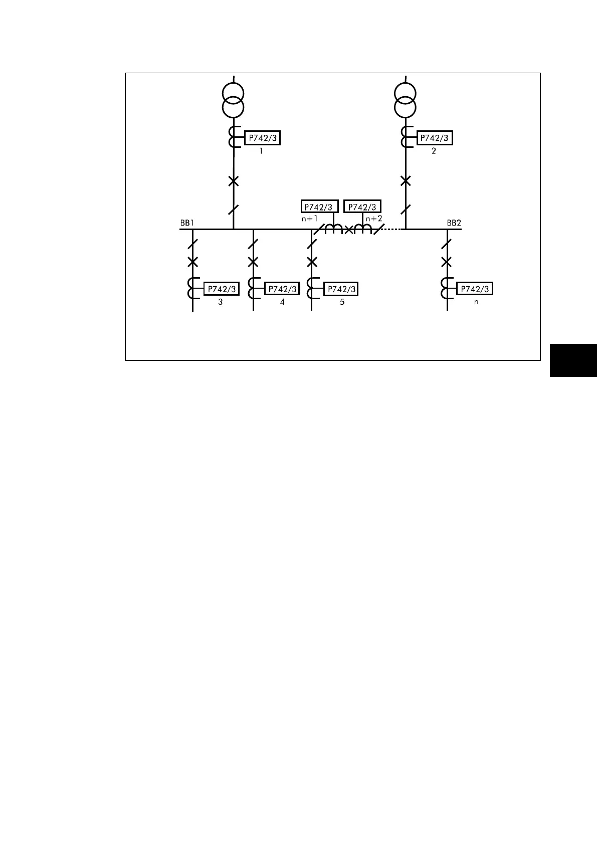
FIGURE 30: SINGLE BUSBAR APPLICATION WITH BUS SECTION CIRCUIT BREAKER
The above example shows a single busbar with a bus section circuit breaker. It is split into
two zones. There are n feeders connected to the busbar. The bus section circuit breaker
has CTs on either side.
This configuration requires 1 central unit and n + 2 peripheral units (the additional peripheral
units being for the bus section CTs). The type of peripheral unit used for each bay will
depend on the i/o requirements of the bay in question.
It is recommended that the CTs for feeder protection are sited such as to overlap with the
CTs defining the limits of each busbar protection zone.