x/EN AP/Na7
-4 MiCOM P74
2. APPLICATION OF INDIVIDUAL PROTECTION FUNCTIONS
The following sections detail individual protection functions in addition to where and how they
may be applied. Each section provides some worked examples on how the settings are
applied to the relay.
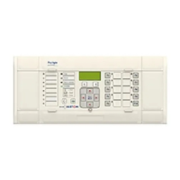
There are three modules that make up the P74x scheme.
The P741 is the Central Unit (CU), whilst the P742 and P743 are both variants of the
Peripheral Unit (PU).
The central unit co-ordinates the scheme, receiving signals from all the peripheral units
associated with the protected busbar(s) and acting on these signals, initiating a bus zone
protection trip when necessary.
One peripheral unit is associated with each CT location, usually one per incomer/feeder and
one or two for each bus coupler/bus section depending on the number of CTs (1 or 2). The
peripheral units acquire the analogue signals from the associated CT and the binary signals
from the auxiliary contacts of the primary plant (CB and isolator(s)). The peripheral units
also incorporate the main circuit breaker failure logic together with backup protection. The
difference between the P742 and P743 is the amount of I/O, the number and type of LEDs
and the function keys that each can accommodate. The P743 allows for increased I/O
(useful in multiple bar applications or where single pole breakers and a transfer bar are
employed), tricolour LEDs, function keys and Ethernet board slot. The main features of the
P74x scheme are summarised below:
• Current differential busbar protection – Phase segregated biased differential protection
(sometimes referred to as low impedance type).
• Provides the main protection element for the scheme. This protection provides high-
speed discriminative protection for all fault types.
• Sensitive differential earth fault protection – provided for high impedance earthed
systems and incorporates bias current control to guarantee stability under external faults.
• Circuit breaker failure protection – two stage breaker fail logic that can be initiated
internally or externally.
• Dead Zone protection – phase and neutral.
• Non-directional phase fault over current protection – provides two stage backup
protection.
• Non-directional earth fault protection – provides two stage backup protection.
• Low Burden – Allows the protection to be installed in series with other equipment on a
common CT secondary.
• Accommodates different CT classes, ratios and manufacturer.
2.1 Busbar Protection
Busbar Biased Current Differential Protection
2.1.1 Busbar Protection Setting guidelines
2.1.1.1 87BB Phase CU settings (Solid Earthed Network Schemes)

 Loading...