CM
Fail & I<] are all set to “Disabled”. Make a note of which elements need to be re-enabled
after testing.
6.3.1.1
Connect the test circuit
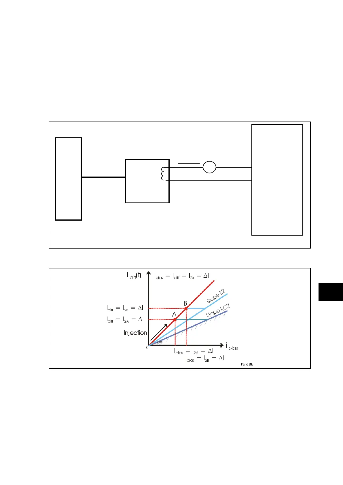
The following tests require an injection test set, able to feed the relays with one or two
currents variable in phase and magnitude.
If only one current is available:
As shown in Figure 7, this method will be used for a distributed solution when only one
peripheral unit is available.
A
P741
Central
Unit
P742/3
Peripheral
Unit 1
FO
Test
Box
I
2
P3749ENa
FIGURE 7: CONNECTION FOR BIAS CHARACTERISTIC TESTING
An increasing current I
2
is injected into a phase (and neutral) of the PU1 which is used as
differential and bias current.
I
diff
= I
bias
= I
2
K2 : Zone percentage bias, Characteristic limit: I
diff
= ID>2
KCZ : Check Zone percentage bias, Characteristic limit: I
diff
= IDCZ>2
In this case, we increase I
2
from 0 to A then B point until the differential element operates:
KCZ : Check Zone percentage bias, Characteristic limit: I
diff
= IDCZ>2, point A
K2 : Zone percentage bias, Characteristic limit: I
diff
= ID>2, point B