P74x/EN MT/N
1, P742, P743
(MT) 11-
1.3.2.2 Replacement of the optional board in P741 (same for P743)
To replace a faulty board, disconnect all connections at the rear of the relay.
The board is secured in the case by two screws accessible from the rear of the relay, one at
the top and another at the bottom, as shown in Figure 6. Remove these screws carefully as
they are not captive in the rear panel of the relay.
Gently pull the optional board forward and out of the case.
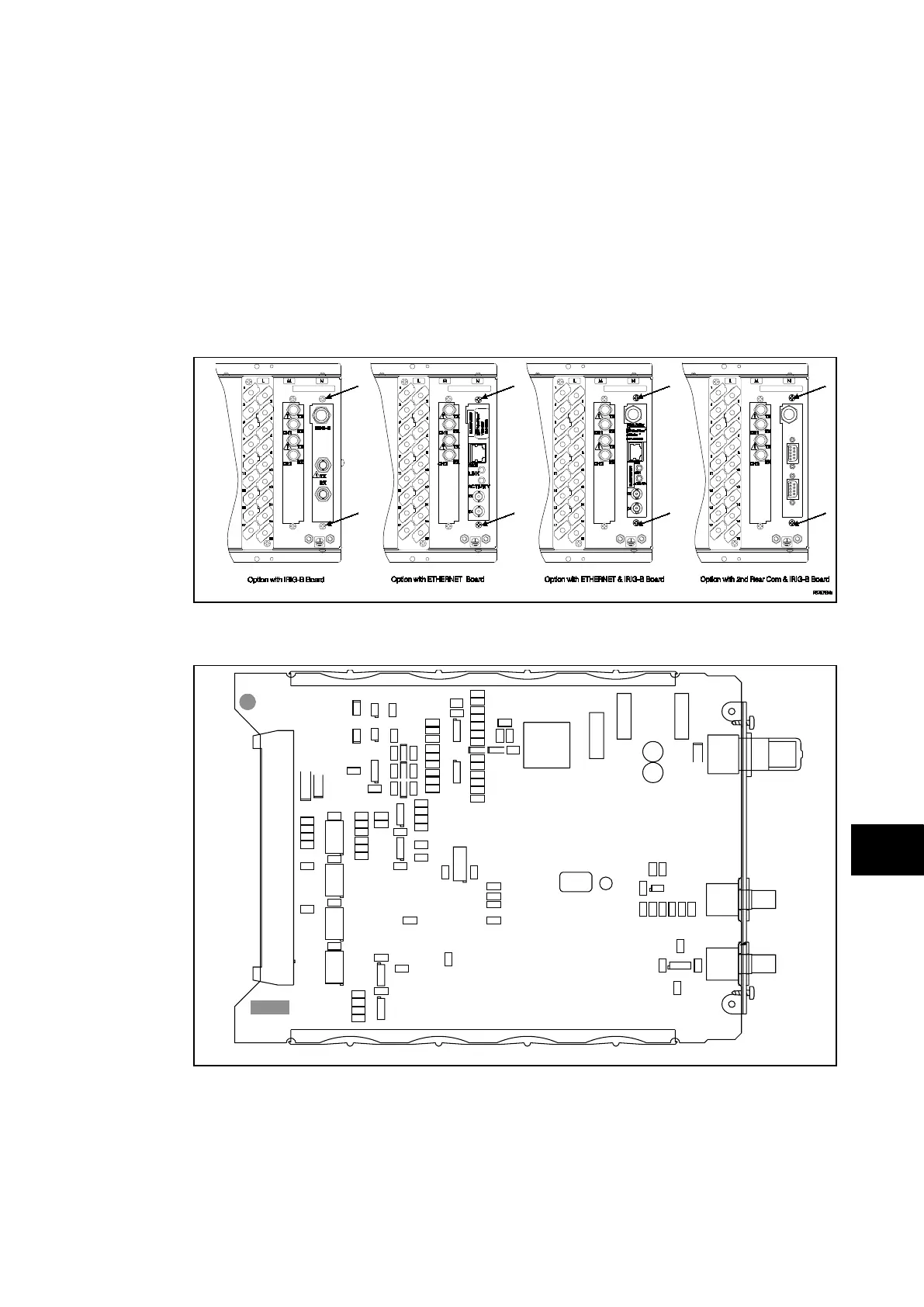
To help identify that the correct board has been removed, Figure 7 shows the layout of the
IRIG-B board with IRIG-B (ZN0007 001 or ZN0049 004) or Ethernet (ZN0049001) or
Ethernet and IRIG-B (ZN0049001 or ZN0049 002 or ZN0049 003) or second rear port.
FIGURE 6: LOCATION OF SECURING SCREWS FOR OPTIONAL BOARD
FIGURE 7: TYPICAL IRIG-B BOARD (P741 only)