x/EN ST/Na7
-
MiCOM P74
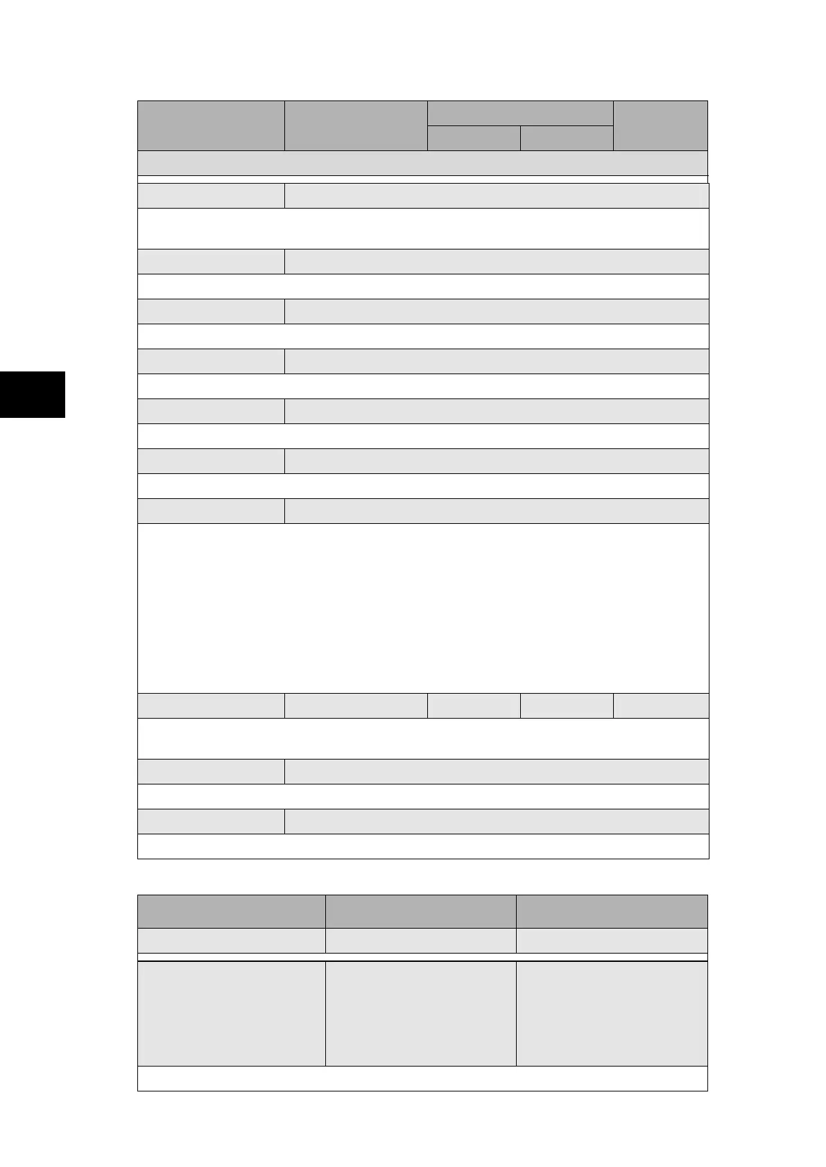
Menu Text Default Setting
Setting Range
Step Size
Min. Max.
SYSTEM DATA
Software Ref. 2
Software Ref. 2 is displayed for a relay with IEC 61850 protocol only and displays the
software version of the Ethernet card.
Opto I/P Status 000000000000000000000000
Duplicate. Displays the status of opto inputs.
Relay O/P Status 0000000000000000
Duplicate. Displays the status of output relays.
Alarm Status 1 00000000000000000000000000000000
32 bits field give status of first 32 alarms (refer to P74x/EN MR for alarm list).
Alarm Status 2 00000000000000000000000000000000
Next 32 alarm status defined.
Alarm Status 3 00000000000000000000000000000000
Next 32 alarm status defined. Assigned specifically for platform alarms.
Access Level 2
Displays the current access level.
Level 0 - No password required - Read access to all settings, alarms, event records
and fault records
Level 1 - Password 1 or 2 required - As level 0 plus: Control commands, e.g. circuit
breaker open/close
Reset of fault and alarm conditions, Reset LEDs
Clearing of event and fault records
Level 2 - Password 2 required - As level 1 plus: All other settings
Password Control 2 0 2 1
Sets the menu access level for the relay. This setting can only be changed when level 2
access is enabled.
Password Level 1 ****
Allows user to change password level 1.
Password Level 2 ****
Allows user to change password level 2.
1.1.2 “Configuration” column (P741 Central Unit)
Menu Text Default Setting Available Settings
CONFIGURATION
Restore Defaults No Operation
No Operation
All Settings
Setting Group 1
Setting Group 2
Setting Group 3
Setting Group 4
Setting to restore a setting group to factory default settings (see also § 1.1.4).