x/EN AP/Na7
-56 MiCOM P74
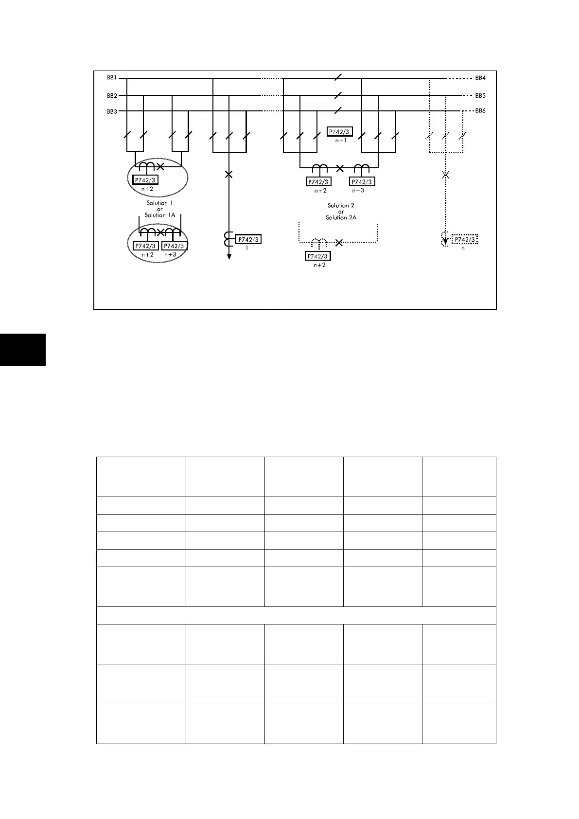
FIGURE 38: TRIPLE BUSBAR APPLICATION WITH BUS COUPLER
AND BUS SECTION
The above example shows a triple busbar with both a bus section and a bus coupler. The
bus section also has additional bus section isolators and allows for bus section bypass. The
scheme is split into six zones. There are n feeders connected to the busbar. The bus
coupler and bus section circuit breakers can have either a single CT (solution 1 and 2) on
one side or CTs on both sides (solution 1a or 2a). This configuration requires 1 central unit
and n plus the following number of peripheral units. The total number of peripheral units
required allows for a peripheral unit for the bus section isolators.
Solution Solution A
1 CT on BC
& 1 CT on BS
Solution B
2 CT on BC
& 2 CT on BS
Solution C
1 CT on BC
& 2 CT on BS
Solution D
2 CT on BC
& 1 CT on BS
Solution 1
Solution 1a
Solution 2
Solution 2a
Number of
peripheral units
required
n + 2 n + 4 n + 3 n + 3
If a second bus coupler is added i.e. one bus coupler either side of the bus section
Using solution 1
for the 2
nd
coupler
Using solution 1a
for the 2
nd
coupler
Number of
peripheral units
required
n + 3 n + 6 n + 4 n + 5
TABLE 6: NUMBER OF REQUIRED PU’S FOR FIGURE 38
The additional peripheral unit being for the bus section isolators is optional.