pplication Notes
P74x/EN AP/N
1, P742, P743 (AP) 6-
15
P742 P742
16
13
P742 P742
14 1
P742 P742
2 17
P742 P742
18
1
P742 P742
2 15
P742 P742
16 3
P742 P742
4 19
P742 P742
20
3
P742 P742
4 17
P742 P742
18 5
P742 P742
6 21
P742 P742
22
5
P742 P742
6 19
P742 P742
20 7
P742 P742
8 23
P742 P742
24
7
P742 P742
8 21
P742 P742
22 9
P742 P742
10 25
P742 P742
26
9
P742 P742
10 23
P742 P742
24 11
P742 P742
12 27
P742 P742
28
11
P742 P742
12 25
P742 P742
26 13
P742 P742
14
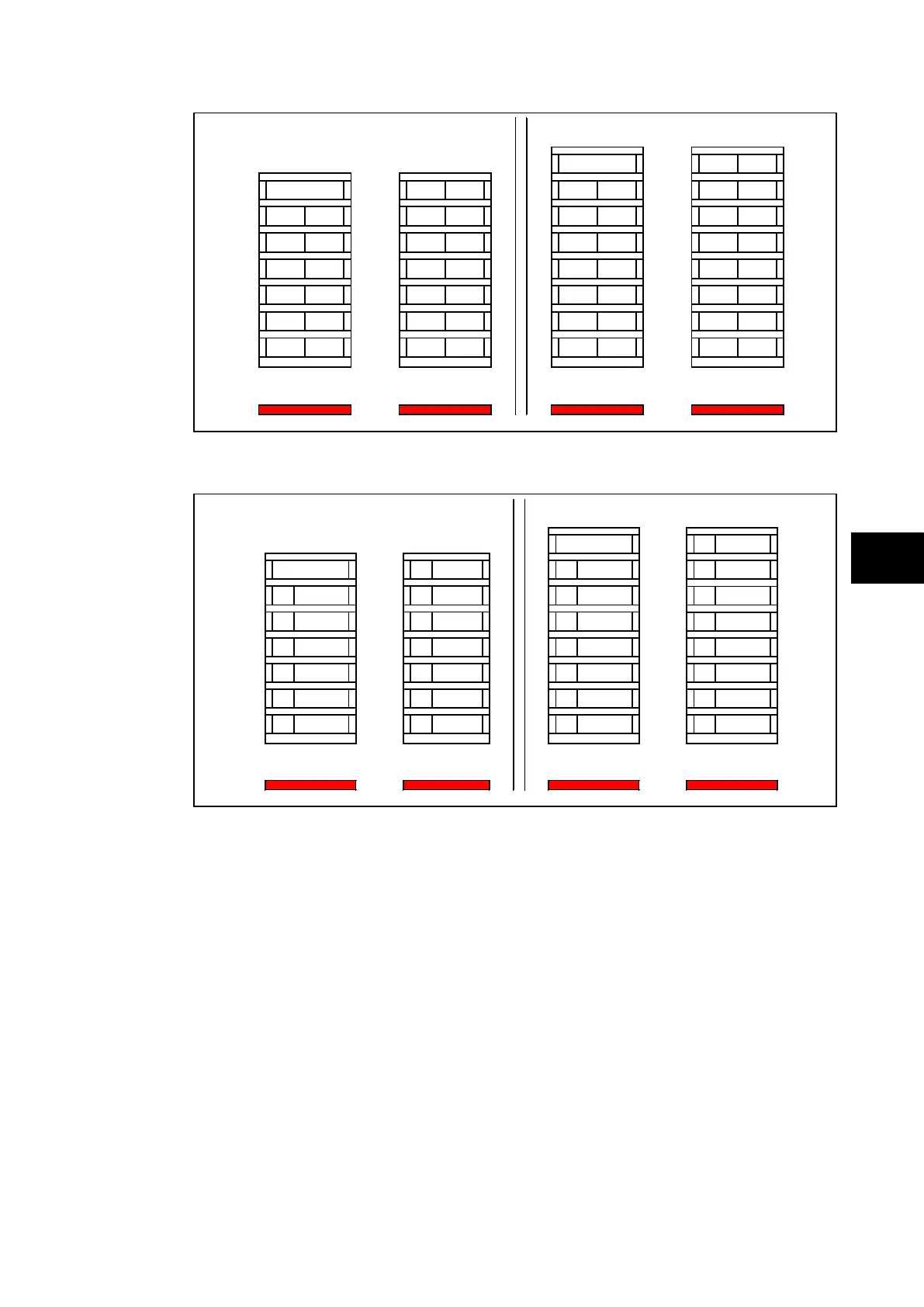
1 P741 and 1 P741 and
12 P742 14 P742 14 P742 14 P742
FIGURE 27: 1 P741 AND P742 WITH P99X TEST BLOCK
P99x P743
8
P99x
P743
7
P99x P743
1
P99x P743
9
P99x P743
1
P99x P743
8
P99x P743
2
P99x P743
10
P99x P743
2
P99x P743
9
P99x P743
3
P99x P743
11
P99x P743
3
P99x P743
10
P99x P743
4
P99x P743
12
P99x P743
4
P99x P743
11
P99x P743
5
P99x P743
13
P99x P743
5
P99x P743
12
P99x P743
6
P99x P743
14
P99x P743
6
P99x P743
13
P99x P743
7
P99x P743
15
1 P741 and 1 P741 and
6 P743 & 6 P99x 7 P743 & 7 P99x 7 P743 & 7 P99x 8 P743 & 8 P99x
FIGURE 28: 1 P741 AND P743 WITH (OR WITHOUT) P99X TEST BLOCK
7.6 Substation Architecture
Due to the flexibility of the differential busbar protection there is an infinite number of busbar
configurations that can be accommodated via the topology. Each may have very different
architecture and, therefore, vary in complexity.
You will find in the following pages topology examples of layouts most frequently
encountered. For each example, the number of central units and peripheral units necessary
to protect the busbars is specified.
Generally, the elements of the protection architecture will be identified in a similar manner to
the principal parts of the substation e.g. by the letters A and B.
Note: A cubicle needs to be considered for a centralised solution whereas if
the peripheral units are distributed and the scheme is distributed there
is no requirement for a dedicated cubicle.
In both cases, and before any delivery, the topology will be thoroughly tested on appropriate
test platforms the scheme is engineered by a GE competency centre).