Measurements and Recording
P74x/EN MR/N
1, P742, P743
(MR) 8-
5. MONITORING TOOLS
5.1 S1
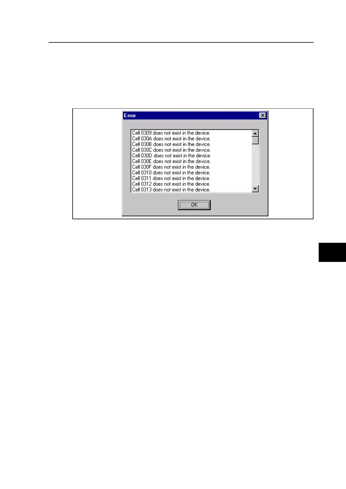
The embedded standard S1 Software monitoring is designed for 8 zones substation.
Consequently, if you open connection with P741 which protects 4 zones substation, there
are error messages to inform you that cells corresponding to topology and measurements of
zone 5 to 8 can not be displayed.
You can use the monitor tool even if this error message appears.
To remove an error message, you have to remove cells in the default file:
Open file celllist.txt with text editor (for example notepad). This file is located in directory
Monitor in the path of S1 install (default is c:\Programmes Files\AREVA\MiCOM S1\Monitor)
Go to line [P741], referring to documentation “Menu Database - P74x/EN GC”
Remove addresses of cell that you don’t want to display after the line /Measurement.
For example, to remove cell [Topology 1, Current node 5], delete line 0405
Save file:
Later, if you want to display a new zone, perform the reverse operation.
5.2 Dynamic Synoptic
A dedicated software monitoring tool has been developed which allows the user to display
on a PC (desktop or laptop) the substation busbar scheme and monitor the status of the
isolators, breakers and CTs as well as analogue measurements and digital values.