P74x/EN OP/N
(OP) 5-
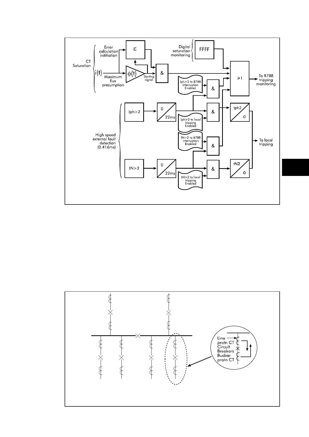
FIGURE 25: DETERMINATION OF SIGNAL QUALITY IN THE PERIPHERAL UNIT
CT Location
There are no restriction imposed as to the location of current transformers within the system,
however, when the topological model is created, the position and orientation of the current
transformers must be defined correctly to ensure the correct operation of the protection.
A suggested current transformer location is to position the current transformer for the busbar
protection, line side of the circuit breaker whilst the line protection current transformers are
positioned busbar side of the circuit breaker. This then covers the largest possible busbar
zone providing an overlap with the line protection therefore eliminating any possible blind
spots. This is shown in Figure below.
FIGURE 26: CT LOCATION