x/EN FD/Na7
-
MiCOM P74
board provides some hardware filtering of the digital signals to remove unwanted noise
before buffering the signals for reading on the parallel data bus.
2.5.3 Universal opto isolated logic inputs
The P741, P742 and P743 relays are fitted with universal opto isolated logic inputs that can
be programmed for the nominal battery voltage of the circuit of which they are a part. i.e.
thereby allowing different voltages for different circuits e.g. signalling, tripping. They
nominally provide a Logic 1 or "ON" value for Voltages 80% of the set voltage and a Logic 0
or "OFF" value for the voltages 60% of the set voltage. This lower value eliminates fleeting
pickups that may occur during a battery earth fault, when stray capacitance may present up
to 50% of battery voltage across an input. Each input has filtering of 7ms. This renders the
input immune to induced noise on the wiring: although this method is secure it can be slow.
In the Opto Config. menu the nominal battery voltage can be selected for all opto inputs by
selecting one of the five standard ratings in the Global Nominal V settings. If Custom is
selected then each opto input can individually be set to a nominal voltage value.
Menu Text Default Setting
Setting Range
Step Size
Min. Max.
OPTO CONFIG
Global Nominal V
24-27 (P741)
48-54 (P742/3)
24 - 27, 30 - 34, 48 - 54, 110 - 125, 220 - 250,
Custom
Opto Input x
24-27 (P741)
48-54 (P742/3)
24 - 27, 30 - 34, 48 - 54, 110 - 125, 220 - 250
2.6 Power supply module (including output relays)
The power supply module contains two PCBs, one for the power supply unit itself and the
other for the output relays (P742 and P743). The power supply board also contains the input
and output hardware for the rear communication port which provides an EIA(RS)485
communication interface.
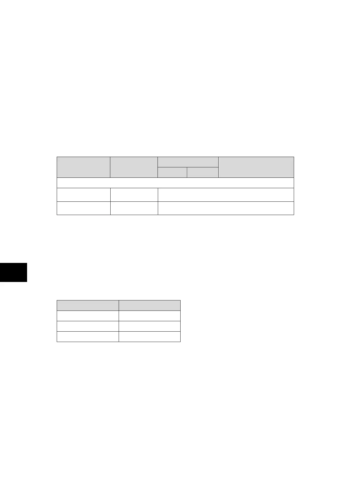
2.7 Power supply board (including EIA(RS)485 communication interface)
One of three different configurations of the power supply board can be fitted to the relay.
This will be specified at the time of order and depends on the nature of the supply voltage
that will be connected to the relay. The three options are shown in table 1 below:
Nominal dc Range Nominal ac Range
24/54 V DC only
48/125 V 30/100 Vrms
110/250 V 100/240 Vrms
Table 1: Power supply options
The outputs from all versions of the power supply module are used to provide isolated power
supply rails to all of the other modules within the relay. Three voltage levels are used within
the relay, 5.1V for all of the digital circuits, 16V for the analogue electronics, e.g. on the
input board, and 22V for driving the output relay coils and for coprocessor and
communication boards 3.3V power supply (through on board DC-DC converter).
All power supply voltages including the 0V ground line are distributed around the relay via
the 64-way ribbon cables. One further voltage level is provided by the power supply board
which is the field voltage of 48V. This is brought out to terminals on the back of the relay so
that it can be used to drive the optically isolated digital inputs.
The two other functions provided by the power supply board are the RS485 communications
interface and the watchdog contacts for the relay. The RS485 interface is used with the
relay’s rear communication port to provide communication using K Bus Courier. The RS485
hardware supports half-duplex communication and provides optical isolation of the serial
data being transmitted and received.