(GS) 3-
1. GETTING STARTED
BEFORE CARRYING OUT ANY WORK ON THE EQUIPMENT, THE USER
SHOULD BE FAMILIAR WITH THE CONTENTS OF THE SAFETY
SECTION/SAFETY GUIDE PXXX-4LM-2 OR LATER ISSUE, THE
TECHNICAL DATA SECTION AND THE RATINGS ON THE EQUIPMENT
RATING LABEL.
1.1 User interfaces and menu structure
The settings and functions of the protection relay can be accessed both from the front panel
keypad and LCD, and via the front and rear communication ports. Information on each of
these methods is given in this section to describe how to start using the relay.
1.2 Introduction to the relay
1.2.1 Front panel
The front panel of the relay is shown in Figure 1 (P742) or 2 (P741 or P743), with the hinged
covers at the top and bottom of the relay shown open. Extra physical protection for the front
panel can be provided by an optional transparent front cover. With the cover in place read
only access to the user interface is possible. Removal of the cover does not compromise the
environmental withstand capability of the product, but allows access to the relay settings.
When full access to the relay keypad is required, for editing the settings, the transparent
cover can be unclipped and removed when the top and bottom covers are open. If the lower
cover is secured with a wire seal, this will need to be removed. Using the side flanges of the
transparent cover, pull the bottom edge away from the relay front panel until it is clear of the
seal tab. The cover can then be moved vertically down to release the two fixing lugs from
their recesses in the front panel.
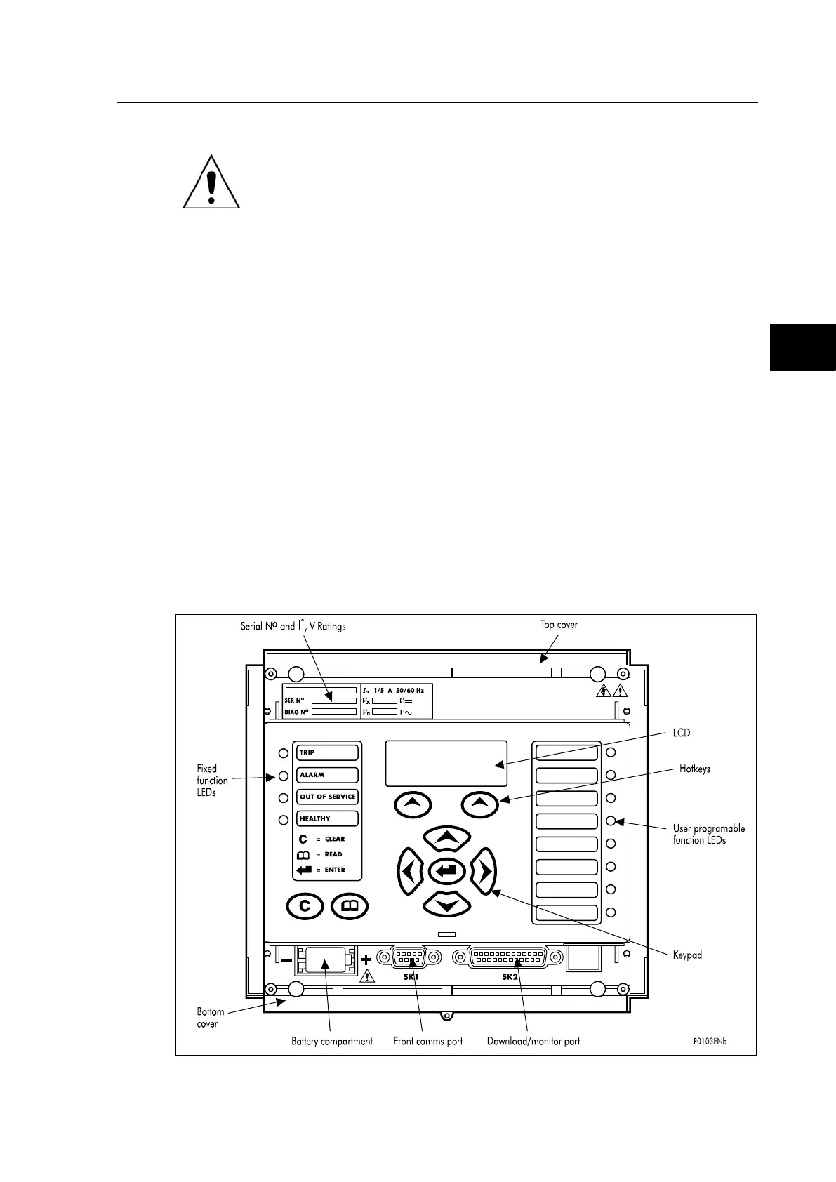
FIGURE 1: RELAY FRONT VIEW (EXAMPLE FOR P742 – 40 TE)
The front panel of the relay includes the following, as indicated in Figure 1: