-
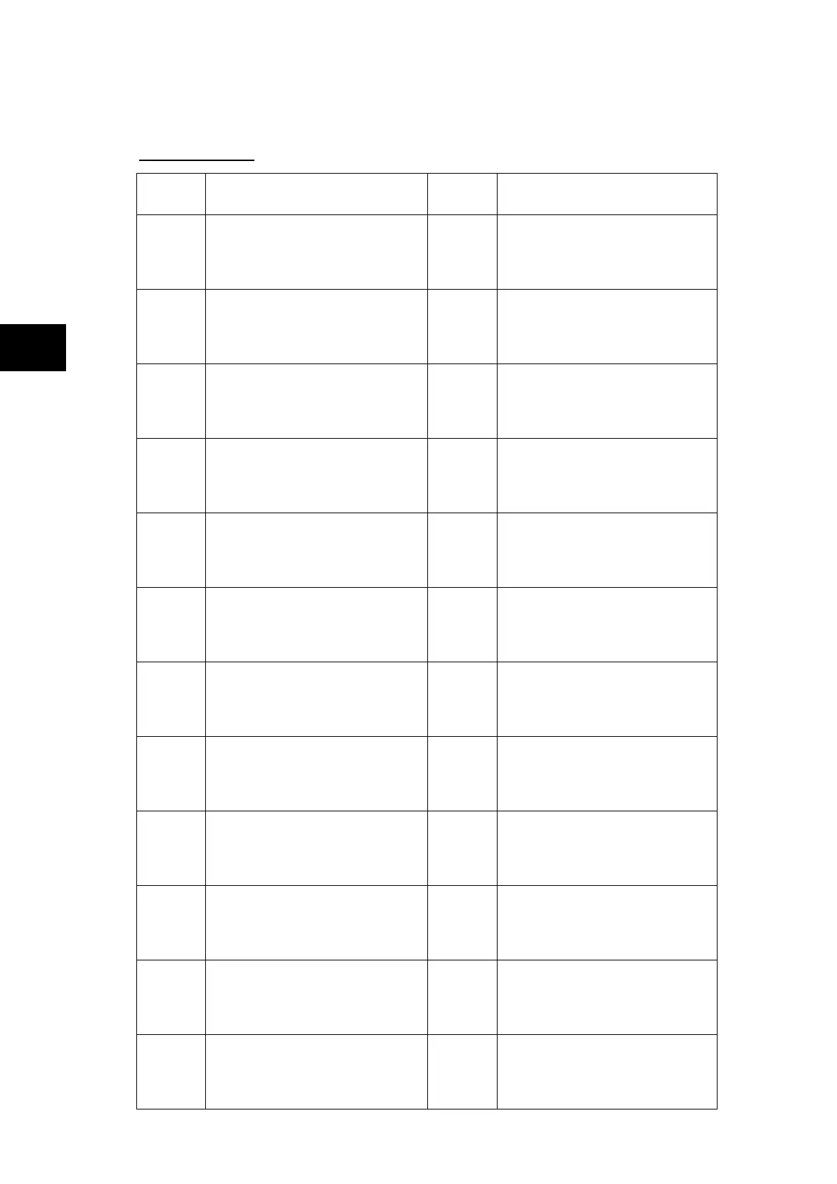
The default mappings for each of the programmable LEDs are as shown in the following
table:
Central Unit P741:
LED
Number
LED Input Connection/Text Latched P74x LED Function Indication
1
LED1 Red
LED1 Yellow
LED1 Green
Yes
87BB fault on phase A
Not used
Not used
2
LED2 Red
LED2 Yellow
LED2 Green
Yes
87BB fault on phase B
Not used
Not used
3
LED3 Red
LED3 Yellow
LED3 Green
Yes
87BB fault on phase C
Not used
Not used
4
LED4 Red
LED4 Yellow
LED4 Green
Yes
50BF Trip Zone 1
87BB & 50BF Trip Zone 1
87BB Trip Zone 1
5
LED5 Red
LED5 Yellow
LED5 Green
Yes
50BF Trip Zone 2
87BB & 50BF Trip Zone 2
87BB Trip Zone 2
6
LED6 Red
LED6 Yellow
LED6 Green
No
Zone 1 blocked by itself
Zone 1 blocked by Check Zone
Zone 1 protected
7
LED7 Red
LED7 Yellow
LED7 Green
No
Zone 2 blocked by itself
Zone 2 blocked by Check Zone
Zone 2 protected
8
LED8 Red
LED8 Yellow
LED8 Green
No
Fiber communication Error
Fiber communication to change
Fiber communication healthy
9
FnKey LED1 Red
FnKey LED1 Yellow
FnKey LED1 Green
No
Zone or CZ circuitry fault block.
Zone or CZ circuitry fault alarm
No Zone or CZ circuitry fault
10
FnKey LED2 Red
FnKey LED2 Yellow
FnKey LED2 Green
No
Zone or CZ PU error fault block.
Zone or CZ PU error fault alarm
No Zone or CZ PU error fault
11
FnKey LED3 Red
FnKey LED3 Yellow
FnKey LED3 Green
No
All protections Disabled
Not used
All protections Not Disabled
12
FnKey LED4 Red
FnKey LED4 Yellow
FnKey LED4 Green
No
Zone 1: 87BB & 50BF blocked
Zone 1: 50BF blocked
Zone 1: protected