x/EN AP/Na7
-42 MiCOM P74
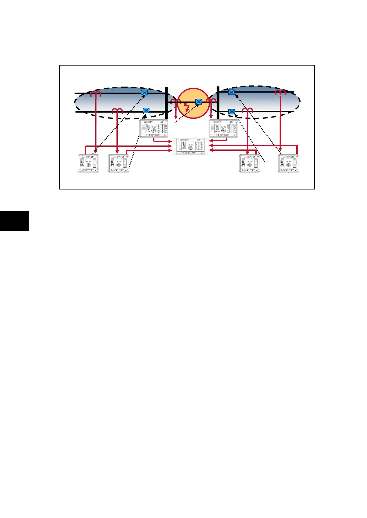
6.5.7 CTs on both sides of coupler, CB closed and fault evolves between CT and CB
FIGURE 26: CT’ ON BOTH SIDES OF BUS COUPLER,
CB CLOSED FAULT OCCURS BETWEEN A CT & THE CB
Treating this as a closed bus section circuit breaker the topology algorithm will have created
a virtual zone that surrounds the circuit breaker with the bus coupler CTs as its limits called
zone 3 in the event report and measurements. This then fully replicates the scheme.
Under normal operating conditions when the circuit breaker is closed load current would flow
through the circuit breaker and hence the virtual zone. The differential current in the two
main zones would equal zero, as the current flowing into the zones would still equal the
current flowing out. This is also the case for the virtual zone around the bus coupler.
However, if a fault was to occur in the virtual zone, current would flow into the virtual zone
and feed the fault. The differential current in the two main zones will still equal zero, as the
current flowing into the zone(s) will still equal the current flowing out, but the differential
current measured in the virtual zone will be equal to that of the fault current.
The main zones would not operate but the virtual zone or zone 3, which surrounds the bus
coupler and has limits at the bus coupler CTs would operate. When the check zone element
is calculated, the differential current seen in the virtual zone or zone 3, which results from the
presence of the fault in the coupler, will confirm the presence of a fault and initiate either (1)
a simultaneous trip of both main zones or (2) a step by step trip of, first the coupler then,
once the topology has been refreshed, the faulty zone 1 (longer fault clearance: around 60
ms + 2 x opening time of the breakers).
(1) Hence, the system reacts to a fault occurring between the CT and the CB simultaneously
tripping both adjacent zones.
Zone 1 I
diff
= I
7
+ I
8
+ I
9
=i
diff
Z1 = 0
Zone 2 I
diff
= I
10
+ I
11
+ I
12
= i
diff
Z2 = 0
Zone 3 I
diff
= I
9
+ I
12
= i
diff
Z2 = i
fault
> (I
D
>2 + k2 x I
Bias
)
Check zone I
diff
= I
7
+ I
8
+ I
10
+ I
11
=i
diff
Z3 = i
fault
(2) The bus coupler can operate first for a fault in the virtual zone or zone 3 and then the
faulty zone 1, zone 2 will remain in service. For such operation a special topology
scheme should be used.
First:
Zone 1 I
diff
= I
7
+ I
8
+ I
9
=i
diff
Z1 = 0
Zone 2 I
diff
= I
10
+ I
11
+ I
12
= i
diff
Z2 = 0
Zone 3 I
diff
= I
9
+ I
12
= i
diff
Z2 = i
fault
> (I
D
>2 + k2 x I
Bias
)
2 CT Coupler with the CB Closed and Fault between a CT and the CB
Check zone
I
diff
= Σ i
diff
= i
7
+ i
8
+ i
10
+ i
11
= i
Fault