x/EN MT/Ma7
-
MiCOM P74
Before fitting the replacement PCB check that the number on the round label adjacent to the
front edge of the PCB matches the slot number into which it will be fitted. If the slot number
is missing or incorrect write the correct slot number on the label.
The replacement PCB should be carefully slotted into the appropriate slot, ensuring that it is
pushed fully back on to the rear terminal blocks and the securing screws are re-fitted.
Reconnect the connections at the rear of the relay.
Refit the front panel using the reverse procedure to that given in section 1.3.2.1. After
refitting and closing the access covers on size 60TE/80TE cases, press at the location of the
hinge-assistance T-pieces so that they click back into the front panel moulding.
Once the relay has been reassembled after repair, it should be recommissioned in
accordance with the instructions in sections 1 to 8 inclusive of the commissioning and
maintenance section P74x/EN CM.
1.3.2.3 Replacement of the input module
The input module comprises of two boards fastened together, the transformer board and the
input board.
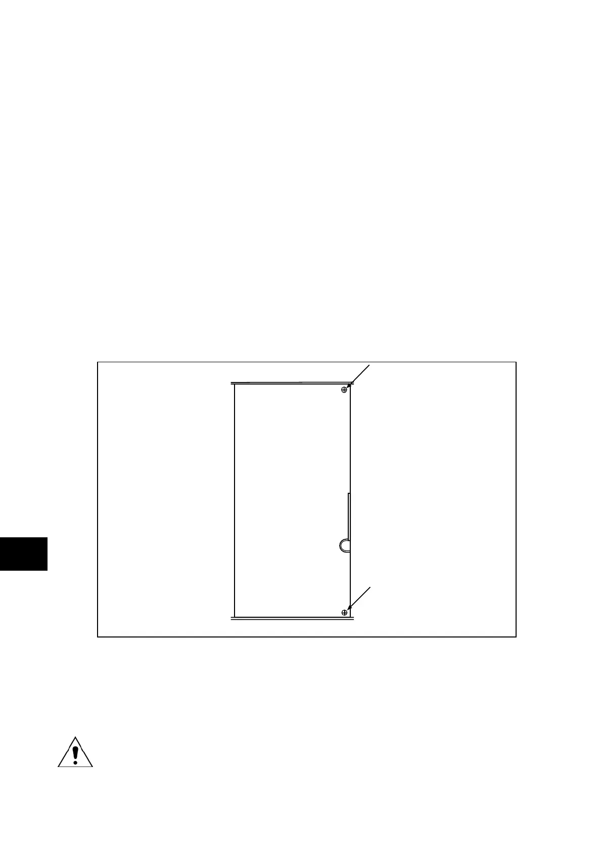
The module is secured in the case by two screws on its right-hand side, accessible from the
front of the relay, as shown in Figure 8. Remove these screws carefully as they are not
captive in the front plate of the module.
Input module
Handle
P3010ENa
FIGURE 8: LOCATION OF SECURING SCREWS FOR INPUT MODULE
On the right-hand side of the analogue input module there is a small metal tab which brings
out a handle. Grasping this handle firmly, pull the module forward, away from the rear
terminal blocks. A reasonable amount of force will be required to achieve this due to the
friction between the contacts of two terminal blocks, one medium duty and one heavy duty.
Note: Care should be taken when withdrawing the input module as it will
suddenly come loose once the friction of the terminal blocks has been
overcome. This is particularly important with unmounted relays as the
metal case will need to be held firmly whilst the module is withdrawn.
Remove the module from the case, taking care as it is heavy because it contains all the
relay’s input voltage and current transformers.