x/EN AP/Na7
-16 MiCOM P74
In the main setting group (usually 1), there is no overcurrent protection, in the next setting
group (usually 2) this overcurrent is enabled (on top of the same setting as in the main
setting group).
The setting group will be changed from “main” to “next” in the PSL.
2.2.4.1 Setting guidelines
For each PU:
• I>1 must be below 80% of the minimum Stub fault level (and if possible bigger than the
maximum load).
• The time delay can be any value.
2.2.5 Circuit Breaker Fail (CBF)
2.2.5.1 Setting guidelines
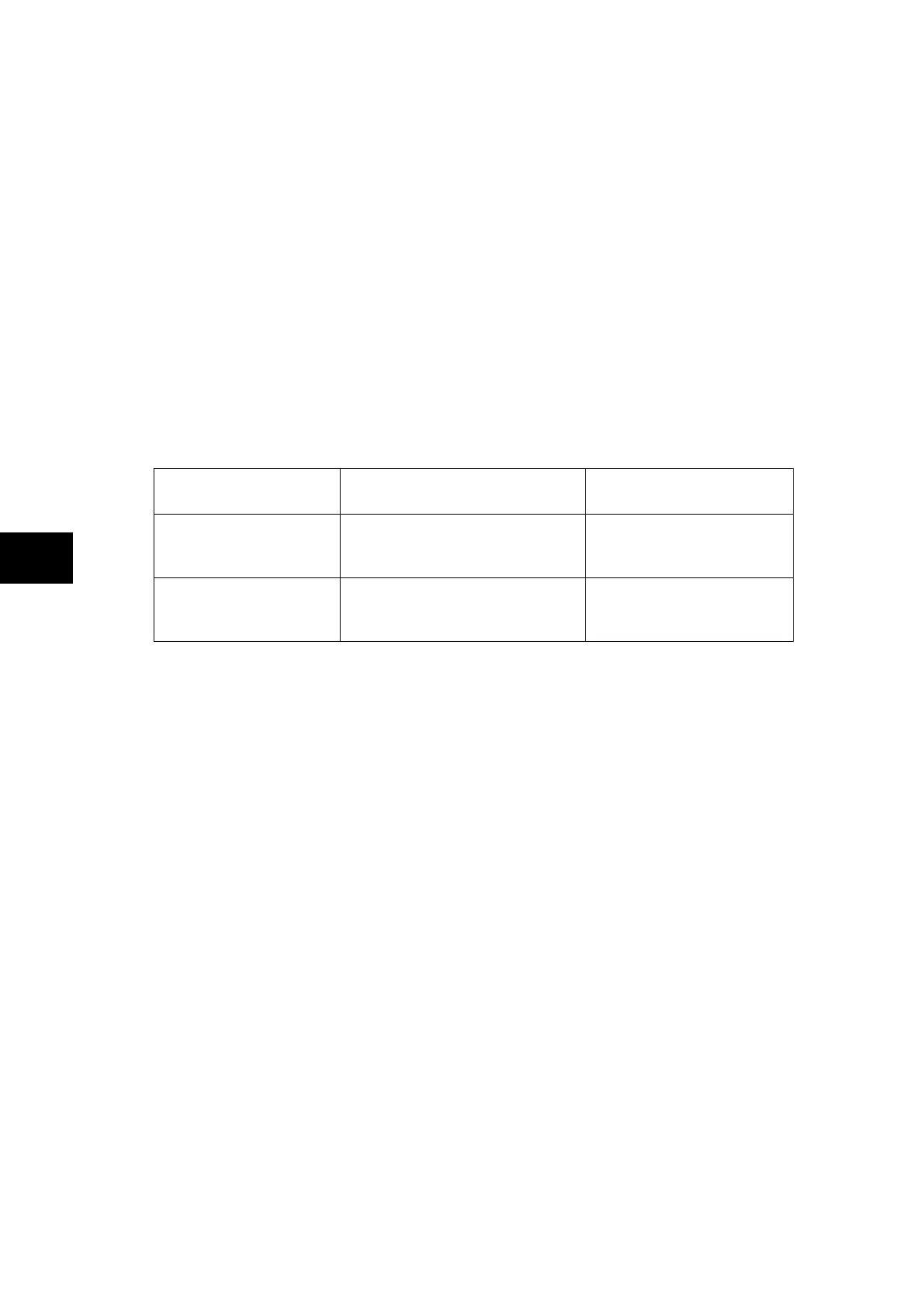
Typical timer settings to use are as follows:
CB fail reset mechanism tBF time delay
Typical delay for 2 cycle
circuit breaker
CB open
CB auxiliary contacts
opening/ closing time (max.) +
error in tBF timer + safety margin
50 + 10 + 50 = 110 ms
Undercurrent elements
CB interrupting time +
undercurrent element (max.) +
safety margin operating time
50 + 15 + 20 = 85 ms
The examples above consider direct tripping of a 2-cycle circuit breaker. Note that where
auxiliary tripping relays are used, an additional 10-15ms must be added to allow for trip relay
operation.
The phase undercurrent settings (Ι<) must be set less than load current, to ensure that Ι<
operation indicates that the circuit breaker pole is open. A typical setting for overhead line or
cable circuits is 20% Ιn, with 5% Ιn common for generator circuit breaker CBF.
2.2.6 External Fault Detection by High-Set Overcurrent or Earth Fault Element
There are feeders where, the short-circuit power is sufficiently low in relation to that of the
busbar or external faults that the CT would saturate for an external fault within 2ms. These
feeders are mainly transformer feeders where the short circuit reactance poses significant
limitations, or weak outfeeders. Thus, knowing the feeder’s maximum possible contribution
to the busbar fault current, it is easy to infer that exceeding this value will indicate an external
fault. In these cases it is just the presence of a high current that will indicate an external fault.
In this case, CT saturation could occur very quickly. The P74x scheme may detect a fault,
but a saturation condition is immediately detected and inhibits tripping.
An ultra high-speed detection is carried out by each of the peripheral units (P742 and P743)
and can generate a blocking signal from the moment of the first sample at 0.42 ms.
In this scenario de-saturation may not occur until after the scheme has eliminated the
saturation condition for the external fault.
This function can be activated independently for phase faults (Ι>2) and for earth faults (Ι
N
>2).