D
IRECTION 5771498-100, REVISION 5 VENUE™ SERVICE MANUAL
Chapter 5 - Venue™Components and Function (Theory) 5-17
PRELIMINARY
Section 5-7
External Input/Output
The Venue™ ultrasound scanner has a connection panel (located at the rear of the eTower) that can
host the connections illustrated below.
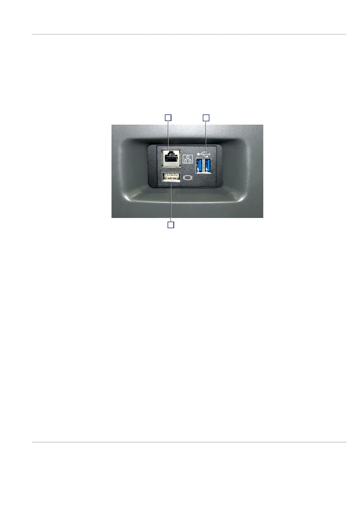
Figure 5-14 shows a view of the Venue™ ultrasound unit interface panel showing external peripheral/
accessory connectors.
1 Ethernet LAN connector — 1000 Base-TX Ethernet IEEE 802.3 (3kV insulation)
2 Dual USB 3.0 connector (not insulated)
3 HDMI connector (not insulated)
NOTE: Non insulated I/O can be populated either by certified medical devices or a self powered device
(powered by the system, not by external AC). All other devices should be connected to the system by
means of additional insulation.
Figure 5-14 View of the Venue™ Peripheral/Accessory Interface Panel

 Loading...


