D
IRECTION 5771498-100, REVISION 5 VENUE™ SERVICE MANUAL
5-18 Section 5-8 - Front End Unit
PRELIMINARY
Section 5-8
Front End Unit
5-8-1 General Information
The Venue™ Front End Unit is designed to support the cSound SW beam-forming architecture for 128
channels.
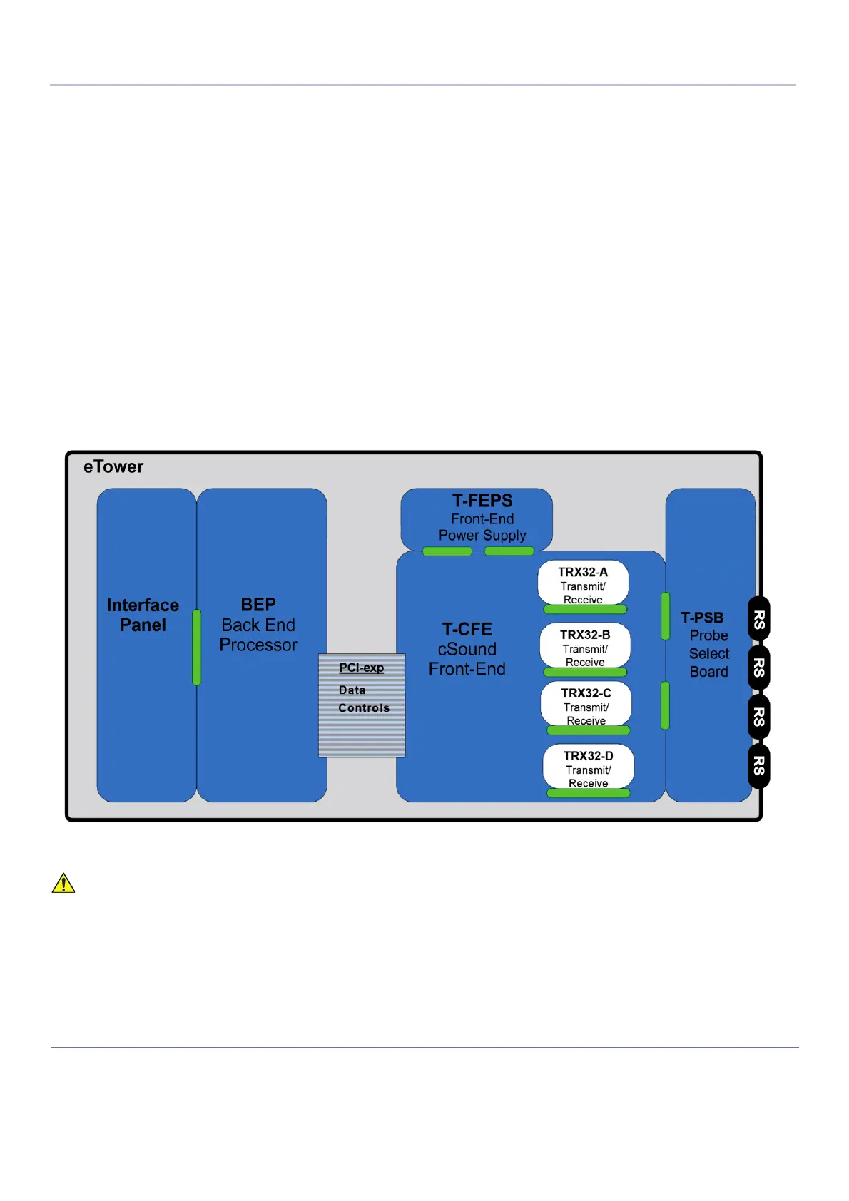
The Front End Unit, located in the door of the Electronic Cage (see Figure 5-15), comprises the
following modules:
- Front End Power Supply (T-FEPS)
See Front End Power Supply (T-FEPS) on page 5 - 20
- Control Front End (T-CFE) Module - includes four Transmit and Receive Modules (TRX32)
See Front End (T-CFE) Board on page 5 - 20 and Back End Processor on page 5-22.
- Probe Selector Module (T-PSB)
For interconnection of probes - see Probe Selection Board (T-PSB) on page 5-21
Figure 5-15 Front End Unit - Location of Components in Electronic Cage Assembly
WHEN OPENING AND CLOSING THE ELECTRONIC CAGE ASSEMBLY, TAKE CARE
NOT TO DAMAGE THE CABLES CONNECTED TO THE BEP.

 Loading...


