8-140 Section 8-6 - Mechanical Parts- Replacement Procedures
D
IRECTION 5771498-100, REVISION 6 VENUE™ SERVICE MANUAL
PRELIMINARY
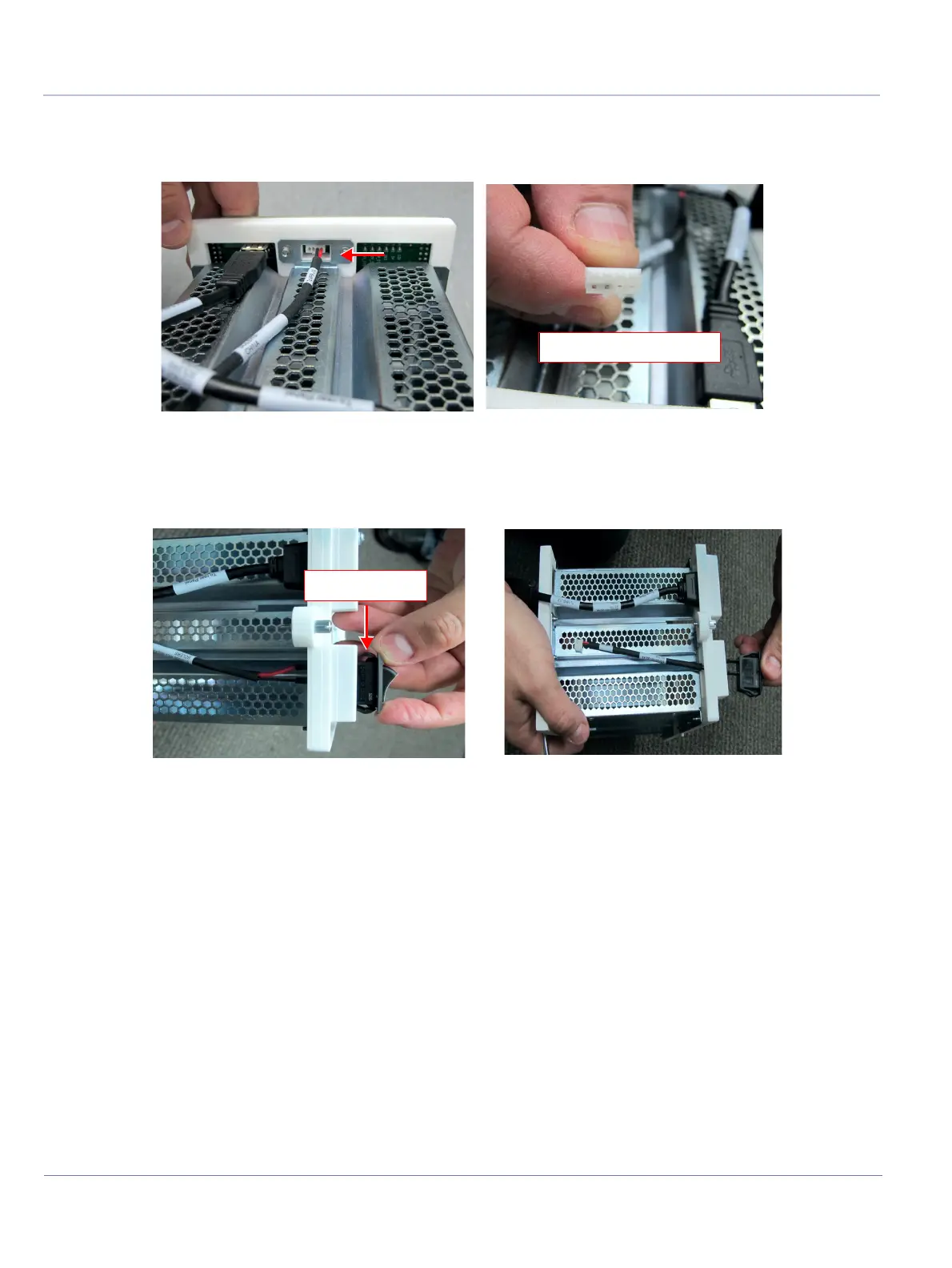
5.) Place the MPB module on a flat surface and disconnect the following cable connectors:
• Disconnect the ON/OFF Switch cable connector from the MPB J10 connector.
• Disconnect the ON/OFF Switch cable connector with the ON/OFF switch from the MPB module
by pressing the securing clips on both sides of the connector.
6.) Remove the ON/OFF Switch Cable.
Figure 8-142 ON/OFF Switch Cable - To MPB J10 Connector
Figure 8-143 ON/OFF Switch Cable with ON/OFF Switch - Connection to MPB Module

 Loading...


