8-150 Section 8-6 - Mechanical Parts- Replacement Procedures
D
IRECTION 5771498-100, REVISION 6 VENUE™ SERVICE MANUAL
PRELIMINARY
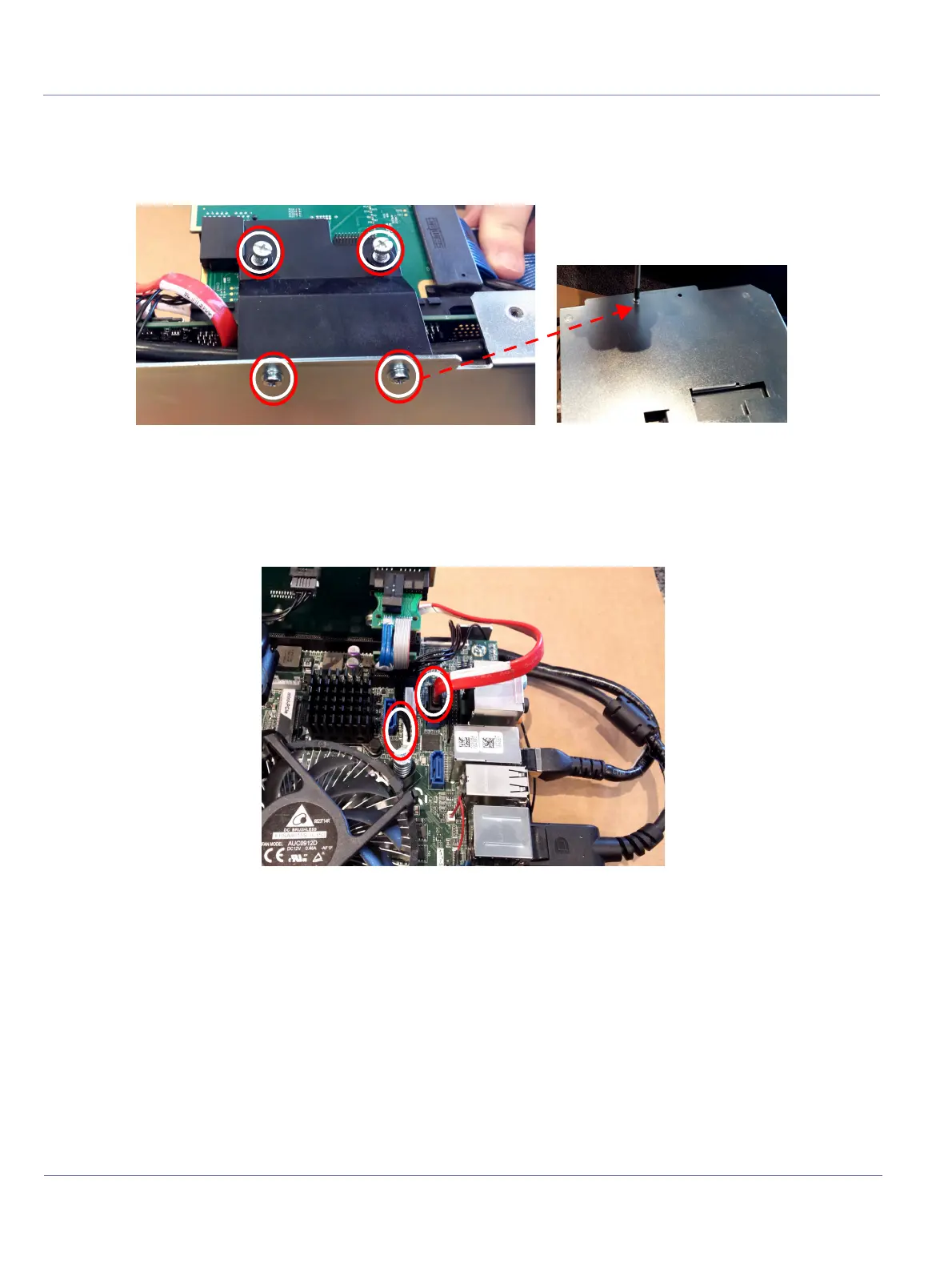
5.) Remove the supporting bracket using an appropriate Phillips screwdriver:
• Release two captive screws
• Release two screws at the bottom of the bracket
6.) Release the following cable connectors:
• SATA DATA BE TO SSD A (red cable): press the latch and pull the cable connector out
• SSD PWR cable: Gently pull the connector towards you
7.) Disconnect the following cables at the back of the BE:
• Two USB connectors
• Network cable
Figure 8-152 Removing BE Supporting Bracket
Figure 8-153 Disconnect SATA DATA and SSD PWR Cables

 Loading...


