8-62 Section 8-4 - System Modules- Replacement Procedures
D
IRECTION 5771498-100, REVISION 6 VENUE™ SERVICE MANUAL
PRELIMINARY
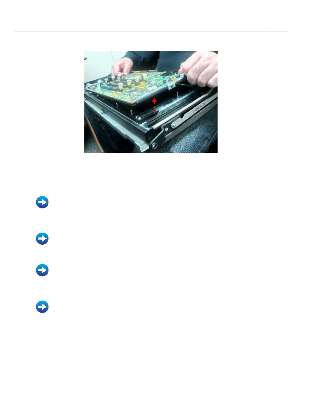
8.) Separate the T-CFE board by pulling the handle upwards, and using the CFE Release Arm.
8-4-11-5 T-CFE Module Installation Procedure
1.) Fit the new T-CFE module and fasten with six screws.
2.) Install the T-TRx 32 modules.
3.) Attach the TTRX BOX and secure with two screws (previously removed).
4.) Install the T-FEPS module.
5) Install the full Front End assembly.
6.) Refit the following covers: Lower Front eTower, Left side eTower, Right Side eTower, and RS Probe
Cover.
Figure 8-51 Separating the T-CFE Board
• TRx Module Installation Procedure
• Front End Power Supply (T-FEPS) Installation Procedure
• Full Front End Installation
• Right Side eTower Cover Installation Procedure
• Left Side eTower Cover Installation Procedure
• Lower Front eTower Cover Installation Procedure
• RS Probe Cover Installation Procedure
 Loading...


