8-70 Section 8-5 - Electronic Boards- Replacement Procedures
D
IRECTION 5771498-100, REVISION 6 VENUE™ SERVICE MANUAL
PRELIMINARY
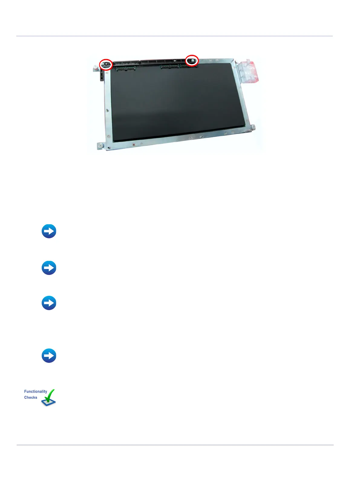
8-5-2-5 T-CFE Release Arm Installation Procedure
1) Install a new T-CFE Release Lever in position on the PSB board.
2) Refit the T-CFE Board.
3.) Insert and tighten the 6 T-CFE Board retaining screw shown in Figure 8-57, above.
4.) Install the T-FEPS module:
5) Install the Front End door assembly:
6.) Refit the following covers: Lower Front eTower, Left side eTower, and Right Side eTower.:
:
7.) Install all accessories.
8.) Turn ON power to the system.
Figure 8-57 Removing CFE Release Arm
• Front End Power Supply Removal Procedure
• Front End Metal Door Replacement
• Right Side eTower Cover Installation Procedure
• Left Side eTower Cover Installation Procedure
• Lower Front eTower Cover Installation Procedure
• RS Probe Cover Removal Procedure
• Accessories - Replacement Procedures
Perform the checks listed in T-CFE Release Arm Replacement Procedure on page 8-217
 Loading...


