Chapter 8 - Replacement Procedures 8-163
D
IRECTION 5771498-100, REVISION 6 VENUE™ SERVICE MANUAL
PRELIMINARY
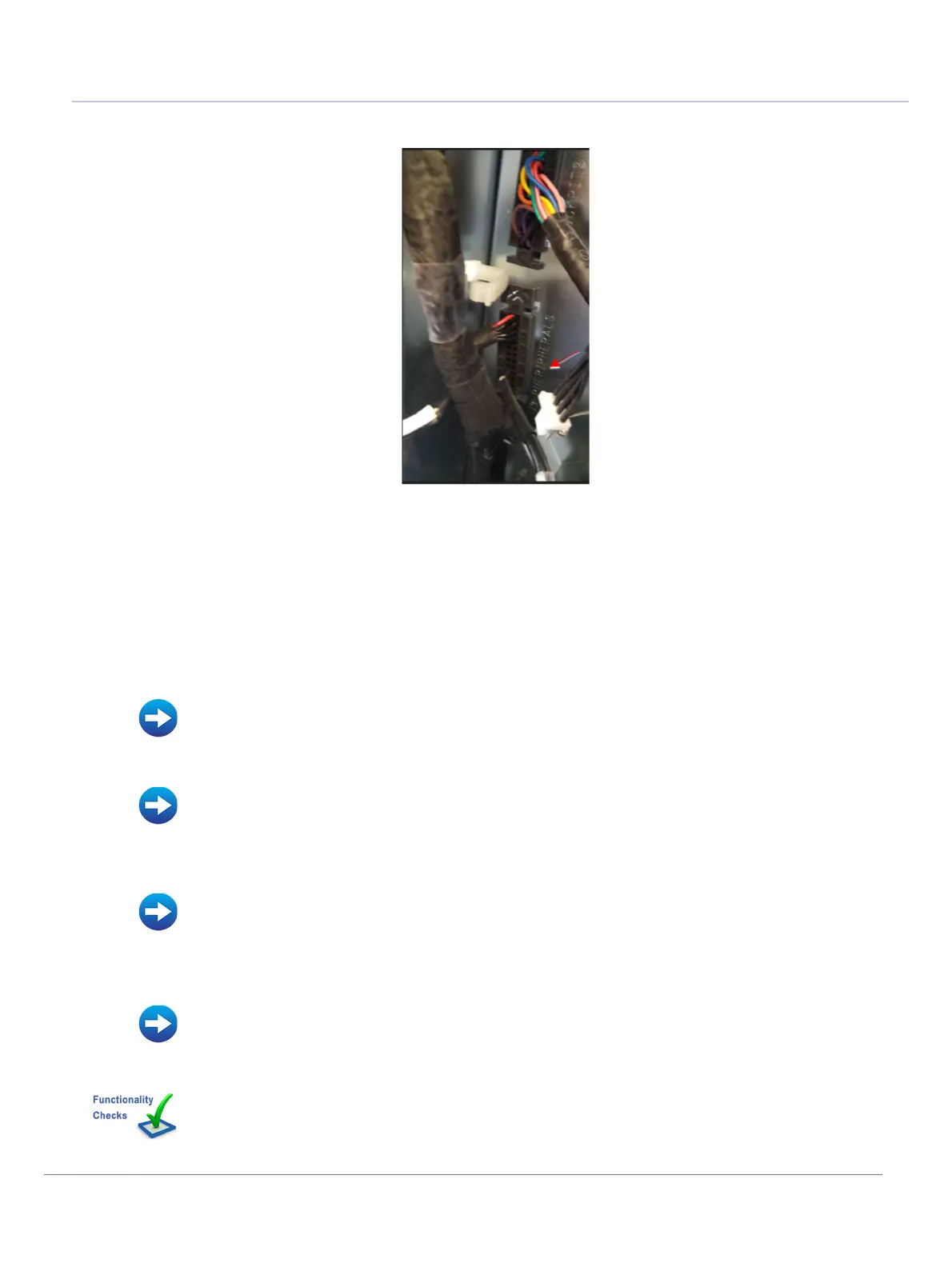
6.) Release the J3 peripherals connector
7.) The cable is released.
8-7-12-5 MPB To Peripherals Harness - FRU Cable Installation Procedure
1.) Connect the cable to J3 connector
2.) Route the cable according to the configuration (if printer is used - route the cable upwards)
3.) Connect the cable to the plastic cable clips
4.) Install the MPB module.
5) Install the MPB Front Metal Door.
6.) Install the following covers: Lower Front eTower, Left side eTower, Right Side eTower and RS
Probe cover.
7.) Install all accessories.
8.) Turn ON power to the system.
Figure 8-172 Release Cable from J3 Connector
• MPB Module Installation Procedure
• MPB Front Metal Door Installation Procedure
• Left Side eTower Cover Installation Procedure
• Right Side eTower Cover Installation Procedure
• Lower Front eTower Cover Installation Procedure
• Accessories - Replacement Procedures
Perform the checks listed in MPB to BIB Control Cable Replacement Procedure on page 8-218
 Loading...


