ADV100 • Functions description and parameters list 139
27 1 = not used
28 1 = not used
29 1 = not used
30 1 = not used
31 1 = not used
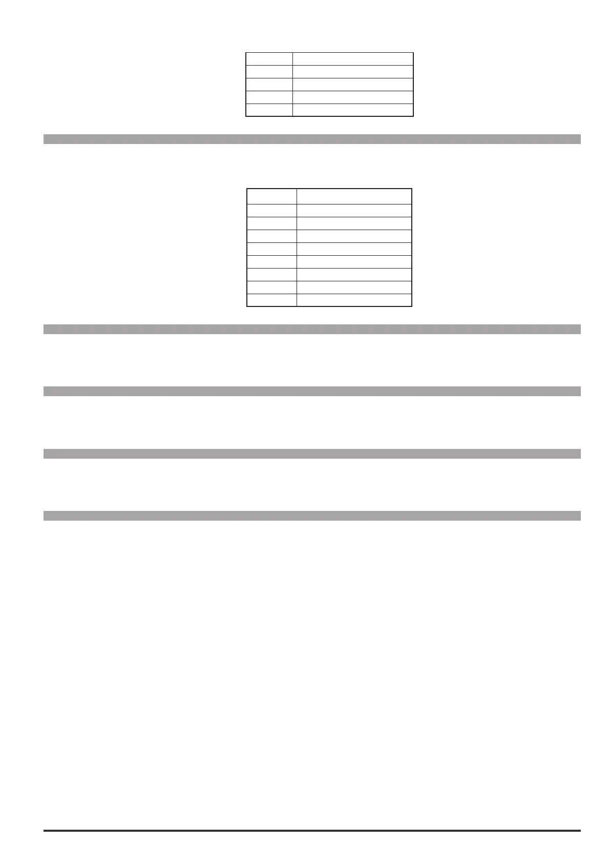
Menu PAR Description UM Type FB BIT Def Min Max Acc Mod
4842 Alarmhistate UINT32 32 0 0 0 ER
This parameter displays the state of alarms 33...64 of the drive.
Bit Description
0 1 = PLC 1 fault active
1 1 = PLC 2 fault active
2 1 = PLC 3 fault active
3 1 = PLC 4 fault active
4 1 = PLC 5 fault active
5 1 = PLC 6 fault active
6 1 = PLC 7 fault active
7 1 = PLC 8 fault active
Menu PAR Description UM Type FB BIT Def Min Max Acc Mod
6000 Null UINT32 32 0 0 0 ER
This signal forces the variable to the zero level (always disabled).
Menu PAR Description UM Type FB BIT Def Min Max Acc Mod
6002 One UINT32 32 1 1 1 ER
This signal forces the variable to level one (always active).
Menu PAR Description UM Type FB BIT Def Min Max Acc Mod
6004 Speedlimitstate BIT 16 0 0 1 ER
This signal is activated when the drive is in the speed limit condition.
Menu PAR Description UM Type FB BIT Def Min Max Acc Mod
6006 Currentlimitstate BIT 16 0 0 1 ER
This signal is activated when the drive is in the current limit condition.