ADV100 • Troubleshooting 145
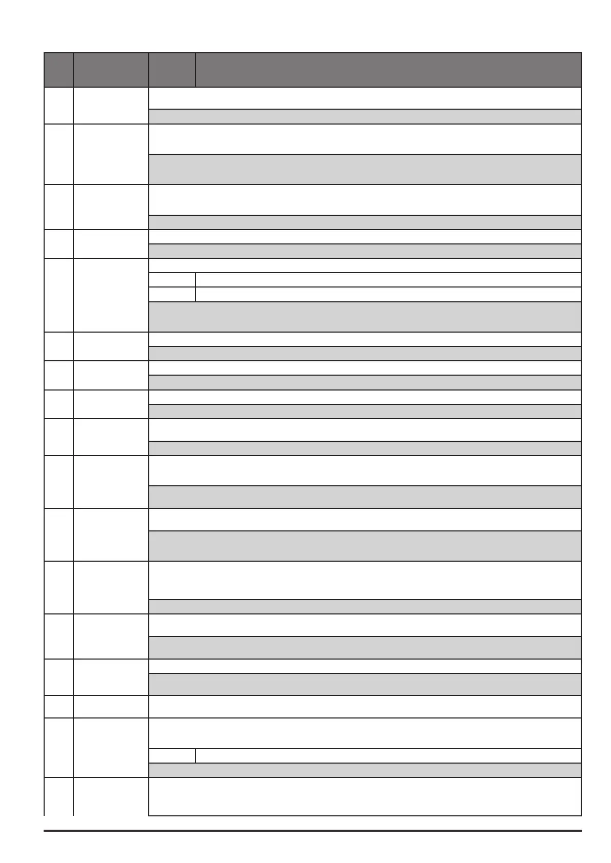
Code Errormessage
shownonthe
display
Sub-code Description
13 Driveoverload
Condition:Drive overload alarm.
The overload threshold of the accumulator of the I²t drive thermal image has been exceeded.
Solution:Check that the size of the drive is suitable for the application.
14 Motoroverload
Condition:Motor overload alarm.
The current absorbed during operation is greater than that specified on the motor data plate. The overload threshold of the accumulator
of the I²t motor thermal image has been exceeded.
Solution:
- Reduce the motor load.
- Increase the size of the motor.
15 Bresoverload
Condition:Braking resistor overload alarm.
The current absorbed by the resistor is greater than the rated current. The overload threshold of the accumulator of the I²t braking resis-
tor thermal image has been exceeded.
Solution:Increase the Watt value of the braking resistor
16 Phaseloss Condition:Power phase loss alarm.
Solution:Check the mains voltage and whether any protections upstream of the drive have been tripped.
17 OptBusfault Condition:Error in the configuration stage or communication error.
XXX0H-X If the first digit to the left of “H” in the alarm sub-code is equal to 0, the error relates to a communication problem.
XXXXH-X If the first digit to the left of “H” in the alarm sub-code is other than 0, the error relates to a configuration problem.
Solution:For configuration errors, check the configuration of the Bus communication, Bus type, Baudrate, address. parameter setting
For communication errors verify wiring, resistance of terminations, interference immunity, timeout settings.
For more details reference should be made to the datasheet of the bus being used.
18 Opt1IOfault Condition:Error in the communication between Regulation and I/O expansion card in slot 1
Solution:Check that it has been inserted correctly.
19 Opt2IOfault Condition:
Solution:
20 OptEncfault Condition:Error in the communication between Regulation and Encoder feedback card.
Solution:Check that it has been inserted correctly.
21 Externalfault
Condition:External alarm present.
A digital input has been programmed as an external alarm, but the +24V voltage is not available on the terminal.
Solution:Check that the terminal screws are tight
22 Speedfbkloss
Condition:Speed feedback loss alarm.
The encoder is not connected, not connected properly or not powered: verify encoder operation by selecting the PAR260Motorspeed
parameter in the MONITOR menu.
Solution:
See parameter 2172 SpdFbkLosscode for information about the cause of the alarm and chapter 10.2 Speedfbkloss [22] alarm
23 Overspeed
Condition:Motor overspeed alarm. The motor speed exceeds the limits set in the PAR670Speedreftoplimand PAR672Speedref
bottomlimparameters.
Solution:
- Limit the speed reference.
- Check that the motor is not driven in overspeed during rotation.
24 Speedrefloss
Condition:Speedreferencelossalarm;occurs if the difference between the speed regulator reference and the actual motor speed is
more than
100 rpm. This condition occurs because the drive is in the current limit condition. It is only available in the Flux Vect OL and Flux Vect OC
mode.
Solution:Check the drive load conditions.
25 Emgstopalarm
Condition:Emergency stop alarm. The Stop key on the keypad was pressed with the Stopkeymodeparameter set to EmgStop&Alarm
in case of Remote->Terminal Strip or Remote->Digital or Local->Terminal Strip mode.
Solution:
Eliminate the reason for which the Stop key on the keypad was pressed and reset the drive.
26 Powerdown Condition:The drive was enabled with no supply voltage at the power section.
Solution:Emergency stop alarm. The Stop key on the keypad was pressed with the Stopkeymodeparameter set to EmgStop&Alarm
in case of Remote->Terminal Strip or Remote->Digital or Local->Terminal Strip mode.
27...
32
NotUsed1...6
33...
40
Plc1fault
...
Plc8fault
Condition:Enabled application developed in the IEC 61131-3 environment has found the conditions for generating this specific alarm to
be true. The meaning of the alarm depends on the type of application. For more information, refer to the documentation concerning the
specific application..
XXXXH-X The XXXXH-X code indicates the reason for the error: make a note of this to discuss it with the service centre.
Solution:Refer to the documentation concerning the enabled application.
41 Watchdog
Condition:this condition can occur during operation when the watchdog micro protection is enabled; the alarm is included in the list of
alarms and alarm log. After this alarm:
- the drive automatically runs a reset
- motor control is not available.