○○○○○○○○○○○○○○○○○○○○○○
8•6 Reference Guide
○○○○○○○○○○○○○○○○○○○○○○
8•6 Reference Guide
Sets the cutoff frequency.
Assignable values: 0 ... 191.
RESONANCE
Sets the filter resonance.
Assignable values: 0 ... 127.
AUDIO OUT
Directs the signal to the stereo audio output out-
puts.
Assignable values:
L+R (Left+Right), L, R.
MIC/LINE ON/OFF (F1)
Switch to activate/deactivate the Mic/Line IN1 and
IN2 jacks. When the inputs are active, the over-
all polyphony is reduced by two voices; if you do
not intend using the Mic/Line inputs, deactivate
them in order to direct the two voices to the inter-
nal PS/GPS sounds.
VOCAL ON/OFF (F3/F4)
Switch for the activation/deactivation of the Vo-
cal Processor. See also the Vocal Processor
chapter.
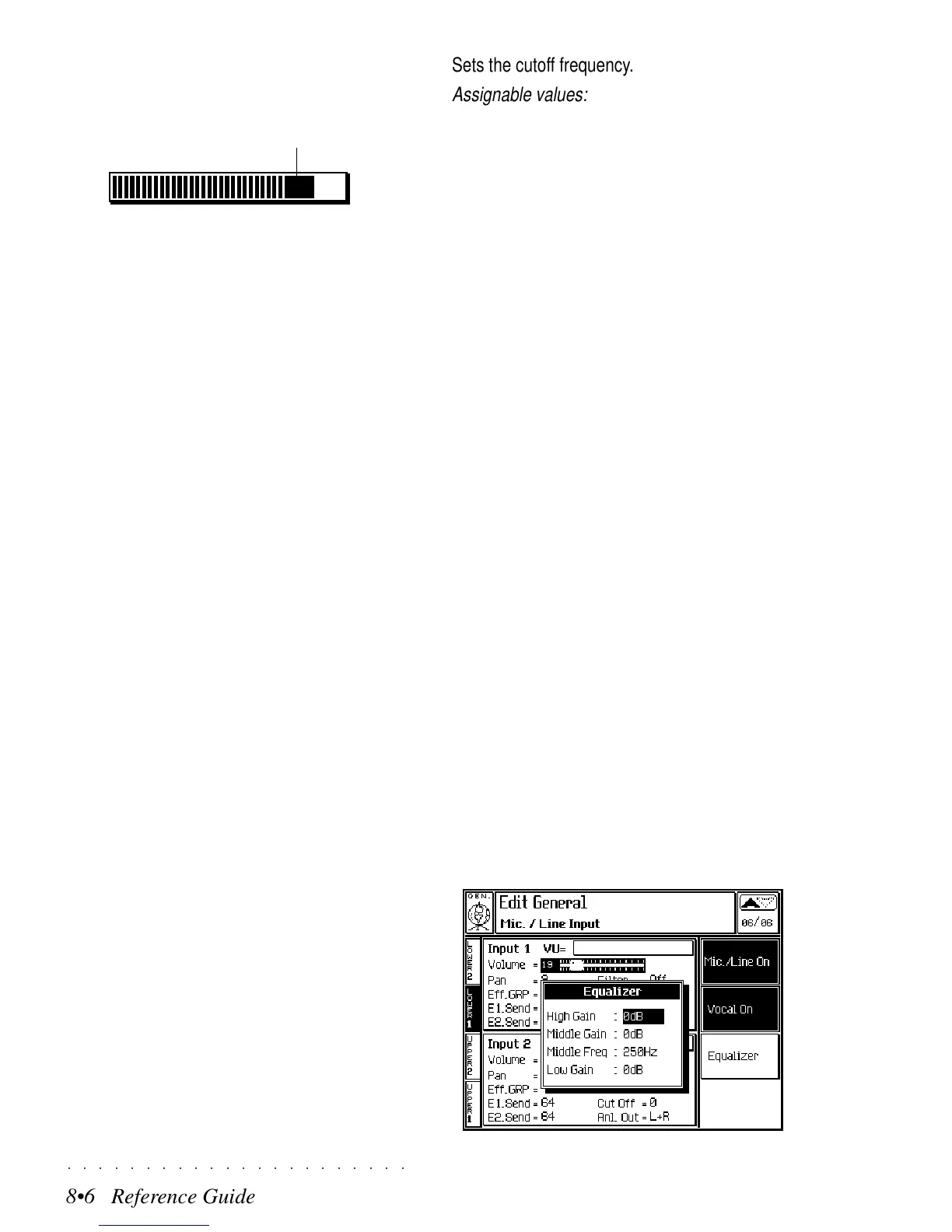
EQUALIZER (F5/F6)
The Equalizer parameters affect the Mic/Line in-
put signals only.
Maximum volume levels can produce “clipping”,
a distortion which can be eliminated by control-
ling the gain.
The VU-meter indicates the level of the input signal. The dark
zone to the extreme right represents clipping (distortion).
clipping
VOLUME
Separate volume control for each input.
Assignable values:
0 ... 127
.
PAN
Determines the position of the input signal within
the stereo panorama.
Assignable values:
-32 (all to the left) ... 0 (cen-
tre) ... +31 (all to the right).
EFF GROUP
Selects the Group of effects A or B.
E1 SEND
Determines the amount of Reverb effect to apply
to the signal.
Assignable values: 0 ... 127.
E2 SEND
Determines the amount of modulation effect to
apply to the signal.
Assignable values: 0 ... 127.
FILTER
Selects a filter type.
Assignable values: Off, LP (Low Pass), HP (High
Pass), BP (Band Pass), PB (Parametric Boost),
PC (Parametric Cut).
CUTOFF
Sets the cutoff frequency.
Assignable values: 0 ... 191.
RESONANCE
Sets the filter resonance.
Assignable values: 0 ... 127.
AUDIO OUT
Directs the signal to the stereo audio output out-
puts.
Assignable values:
L+R (Left+Right), L, R.
MIC/LINE ON/OFF (F1)
Switch to activate/deactivate the Mic/Line IN1 and
IN2 jacks. When the inputs are active, the over-
all polyphony is reduced by two voices; if you do
not intend using the Mic/Line inputs, deactivate
them in order to direct the two voices to the inter-
nal PS/GPS sounds.
VOCAL ON/OFF (F3/F4)
Switch for the activation/deactivation of the Vo-
cal Processor. See also the Vocal Processor
chapter.
EQUALIZER (F5/F6)
The Equalizer parameters affect the Mic/Line in-
put signals only.
Maximum volume levels can produce “clipping”,
a distortion which can be eliminated by control-
ling the gain.
The VU-meter indicates the level of the input signal. The dark
zone to the extreme right represents clipping (distortion).
clipping
VOLUME
Separate volume control for each input.
Assignable values:
0 ... 127
.
PAN
Determines the position of the input signal within
the stereo panorama.
Assignable values:
-32 (all to the left) ... 0 (cen-
tre) ... +31 (all to the right).
EFF GROUP
Selects the Group of effects A or B.
E1 SEND
Determines the amount of Reverb effect to apply
to the signal.
Assignable values: 0 ... 127.
E2 SEND
Determines the amount of modulation effect to
apply to the signal.
Assignable values: 0 ... 127.
FILTER
Selects a filter type.
Assignable values: Off, LP (Low Pass), HP (High
Pass), BP (Band Pass), PB (Parametric Boost),
PC (Parametric Cut).
CUTOFF
○○○○○○○○○○○○○○○○○○○○○○
8•6 Reference Guide
○○○○○○○○○○○○○○○○○○○○○○
8•6 Reference Guide
Sets the cutoff frequency.
Assignable values: 0 ... 191.
RESONANCE
Sets the filter resonance.
Assignable values: 0 ... 127.
AUDIO OUT
Directs the signal to the stereo audio output out-
puts.
Assignable values:
L+R (Left+Right), L, R.
MIC/LINE ON/OFF (F1)
Switch to activate/deactivate the Mic/Line IN1 and
IN2 jacks. When the inputs are active, the over-
all polyphony is reduced by two voices; if you do
not intend using the Mic/Line inputs, deactivate
them in order to direct the two voices to the inter-
nal PS/GPS sounds.
VOCAL ON/OFF (F3/F4)
Switch for the activation/deactivation of the Vo-
cal Processor. See also the Vocal Processor
chapter.
EQUALIZER (F5/F6)
The Equalizer parameters affect the Mic/Line in-
put signals only.
Maximum volume levels can produce “clipping”,
a distortion which can be eliminated by control-
ling the gain.
The VU-meter indicates the level of the input signal. The dark
zone to the extreme right represents clipping (distortion).
clipping
VOLUME
Separate volume control for each input.
Assignable values:
0 ... 127
.
PAN
Determines the position of the input signal within
the stereo panorama.
Assignable values:
-32 (all to the left) ... 0 (cen-
tre) ... +31 (all to the right).
EFF GROUP
Selects the Group of effects A or B.
E1 SEND
Determines the amount of Reverb effect to apply
to the signal.
Assignable values: 0 ... 127.
E2 SEND
Determines the amount of modulation effect to
apply to the signal.
Assignable values: 0 ... 127.
FILTER
Selects a filter type.
Assignable values: Off, LP (Low Pass), HP (High
Pass), BP (Band Pass), PB (Parametric Boost),
PC (Parametric Cut).
CUTOFF
 Loading...